
Process and apparatus for the drying of yellowcake

a technology of yellowcake and processing equipment, which is applied in lighting and heating equipment, inorganic chemistry, uranium oxides/hydroxides, etc., can solve the problems of high cost, high energy consumption, and high energy consumption of washing, dewatering and drying processes traditionally adopted to dry yellowcake, so as to improve separation, facilitate processing, and improve the effect of drying ra

Inactive Publication Date: 2010-02-18
ADELAIDE CONTROL ENGINEERS
View PDF2 Cites 0 Cited by
  • Summary
  • Abstract
  • Description
  • Claims
  • Application Information

AI Technical Summary

Benefits of technology

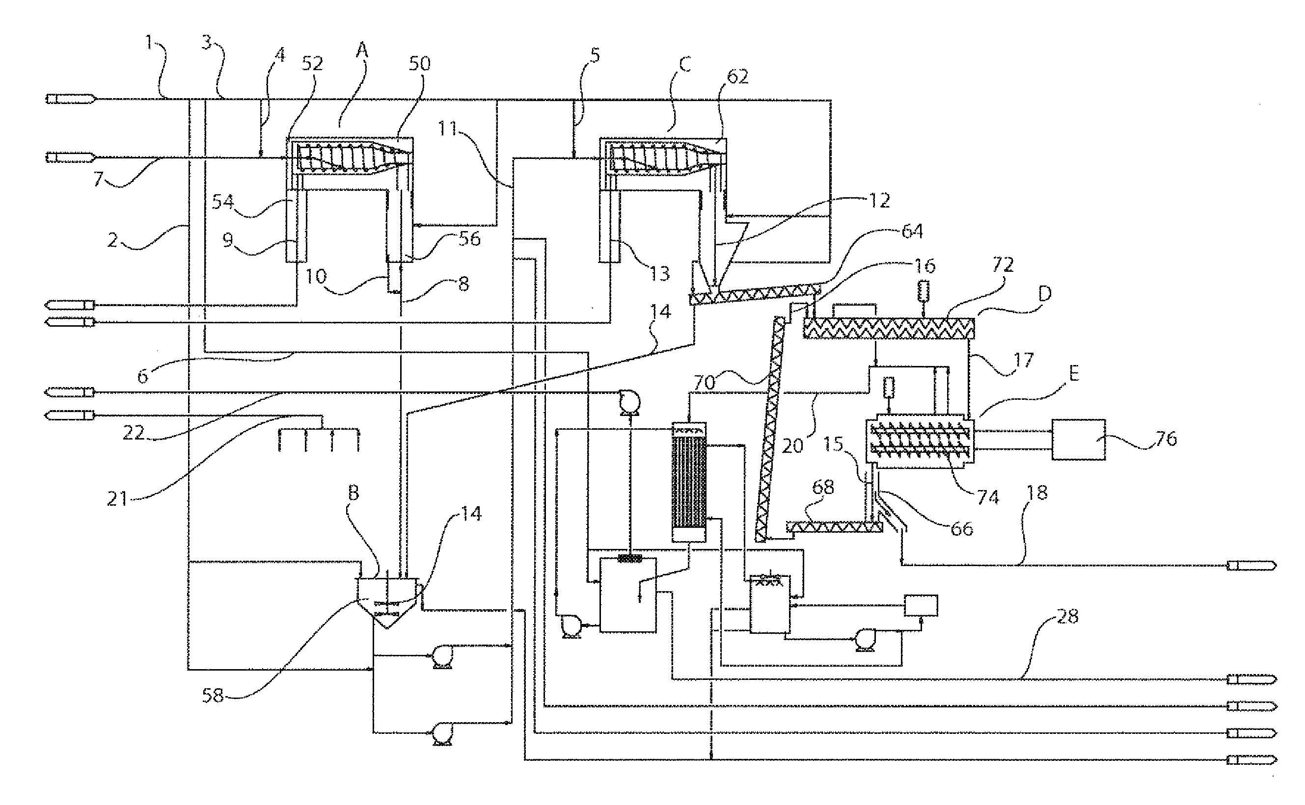
[0067]The use of a centrifuge as the preferred type of dewatering means is advantageous for several reasons. Firstly, in traditional processes, the discharge from the chemical treatment plant (as the feed slurry for the process of the present invention) is directed to an apparatus that does not provide much agitation of the liquid, depending instead upon gravity separation to produce a slurry of acceptable concentration. However, a centrifuge of course operates by means of centrifugal force rather than normal gravity force and is therefore able to provide improved separation at higher processing rates. Also, because of the nature of the movement of a slurry within a centrifuge, there is better agitation to promote the dissolving of the water-soluble impurities from the first dewatered solids cake.
[0071]The re-slurrying (which is often called “re-hydration” or simply “washing”) that occurs in the re-slurry tank is preferably a continuous process with the discharge (the intermediate slurry) being directed to the second dewatering stage mentioned above. In this respect, while it is common for a re-slurrying process to be conducted in line by simply adding water to a flowing stream, this can result in the formation of a slurry of varying strength and can create uneven contact between the re-slurry liquid and the soluble impurities in the stream. By carrying out the re-slurrying in an agitated tank (as is preferred in the present invention), these short-comings are avoided and the extended contact time provides more scope to dissolve the impurities.
[0078]The mixing of the second dewatered solids cake with previously-dried product is an important part of the process of the present invention where the low solids content uranium rich feed slurry is of the uranium peroxide type. The present inventors have determined that ineffective mixing can result in agglomeration of the infeed to the dryer into “balls” which dry only on the outside leaving moisture trapped within the ball. As there are commercial limits to the amount of moisture that can be contained in the final dried uranium peroxide yellowcake, which limits are very difficult to achieve should the mixing result in ball formation, this part of the process of the present invention is particularly beneficial. Indeed, in the preferred form, where the mixer is a twin-screw mixer, the propensity for ball formation is even further minimised because of the continuous shearing action on the mix.
[0080]In the production of dried uranium peroxide yellowcake by means of traditional dryers, such as externally-heated dryers, the dryer is normally of the “porcupine” type. Such dryers often consist of a rotor with heated paddles arranged in a screw format which act in a similar manner to a single screw conveyor and transfer the material from an infeed end to an outfeed end during the drying process. However, such dryers have the inherent disadvantages of single screw conveyors and may, under unfavourable circumstances, cease to transfer product but merely have it rotate with the rotor. The use in the present invention of the preferred form of twin-screw or quad-screw dryer with continuous flights is expected to overcome this transfer problem and provide for better contact between the product and the heating surfaces.

Problems solved by technology

Typically, the washing, dewatering and drying processes that have traditionally been adopted to dry yellowcake have been reasonably energy intensive.
They have also required large quantities of water which, given the often remote locations of the uranium ore deposits, introduces significant cost issues.

Method used


Image

  • Process and apparatus for the drying of yellowcake
  • Process and apparatus for the drying of yellowcake
  • Process and apparatus for the drying of yellowcake

Examples


Embodiment Construction

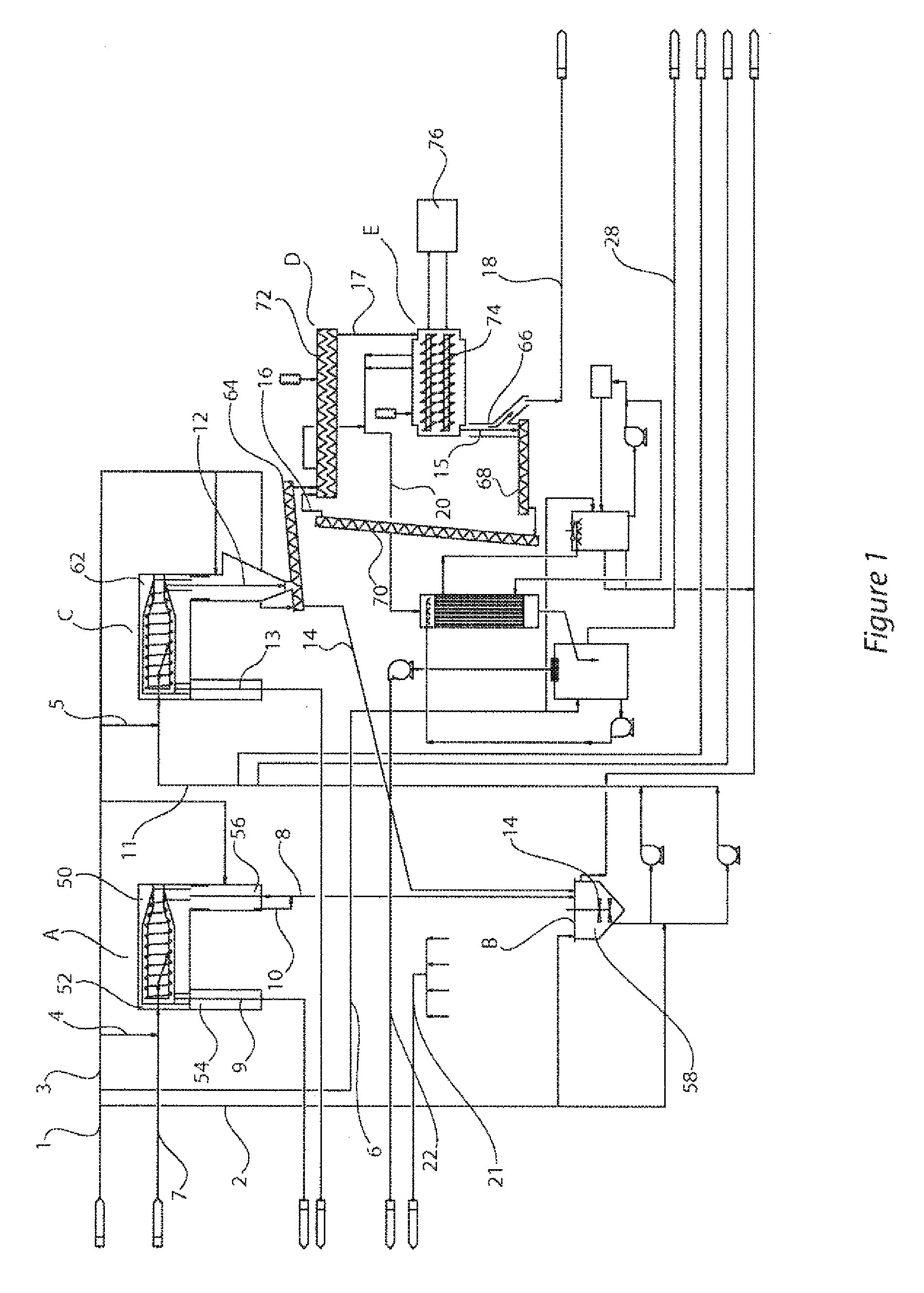
[0086]FIG. 1 provides a flow diagram of a preferred embodiment of the process of the present invention, being one that is a process for the drying of uranium peroxide yellowcake. The main product flow path has been bolded to distinguish it from ancillary flow paths (such as the paths that show the movement of water, off-gases, centrate, and the like) as will be explained later.

[0087]The main product flow path shows a low solids content, uranium rich feed slurry 7 of the uranium peroxide type being fed to a first dewatering means A for dewatering to produce a first dewatered solids cake 8 with a solids content higher than the feed slurry 7. In one form, it is envisaged that the feed slurry will have the following approximate composition:

Feed Slurry - Typical CompositionSolids %2 to 20% (w / w)UO4•2H2O Concentration70 to 90% of solidsSpecific Gravity1.05 to 1.1Sulphates5 to 20 g / LChlorides1,000 to 30,000 ppmpH5 to 6.5

[0088]The first dewatering means A is preferably a centrifuge 50 that ...


PUM

PropertyMeasurementUnit
Fractionaaaaaaaaaa
Fractionaaaaaaaaaa
Fractionaaaaaaaaaa

Abstract

A process for the drying of yellowcake, the yellowcake initially being in the form of a low solids content, uranium rich feed slurry, the process including the stages of: a. dewatering the feed slurry to produce a first dewatered solids cake with a solids content higher than the feed slurry; b. re-slurrying the first dewatered solids cake with sufficient water to dissolve at least some impurities and to produce an intermediate slurry with a solids content lower than the first dewatered solids cake; c. dewatering the intermediate slurry to produce a second dewatered solids cake with a solids content higher than the feed slurry; and d. drying the second dewatered solids cake to produce dried yellowcake.

Description

RELATED APPLICATIONS[0001]This international patent application claims priority from Australian provisional patent application 2007900945, the specification of which is hereby incorporated by reference.FIELD OF THE INVENTION[0002]The present invention relates to a process and apparatus for the drying of yellowcake, yellowcake being an intermediate product formed during the processing of uranium bearing ores to produce, for example, uranium peroxide (UO4.2H2O) for subsequent conversion or enrichment to form commercial amounts of uranium.BACKGROUND OF THE INVENTION[0003]The mining and processing of uranium bearing ores generally always utilizes a leaching process (and thus the use of a lixiviant, such as an aqueous carbonate-bicarbonate solution or an acid solution) to leach the uranium from its accompanying gangue material in the ore body. Such leaching operations may be conducted in conjunction with surface milling operations where the uranium is mined (often in open-pits) and then ...

Claims


Application Information

Patent Timeline
IPC IPC(8): C01G43/00F26B17/30
CPCC01G43/00C01G43/01C22B60/0286F26B2200/18F26B7/00F26B17/20F26B5/08
Inventor JOBLING, GLENN
Owner ADELAIDE CONTROL ENGINEERS
Learn More