
Friction-Welded Part and Method of Friction Welding

a friction welding and friction welding technology, applied in the direction of manufacturing tools, machines/engines, transportation and packaging, etc., can solve the problems of unavoidable heat affected zones, difficult and complicated difficult design of suspension parts, so as to limit the increase in time and cost, reduce the volume of aluminum alloy removed as shavings, and reduce the effect of heat affected zones

Active Publication Date: 2010-02-18
NIPPON LIGHT METAL CO LTD +1
View PDF3 Cites 13 Cited by
  • Summary
  • Abstract
  • Description
  • Claims
  • Application Information

AI Technical Summary

Benefits of technology

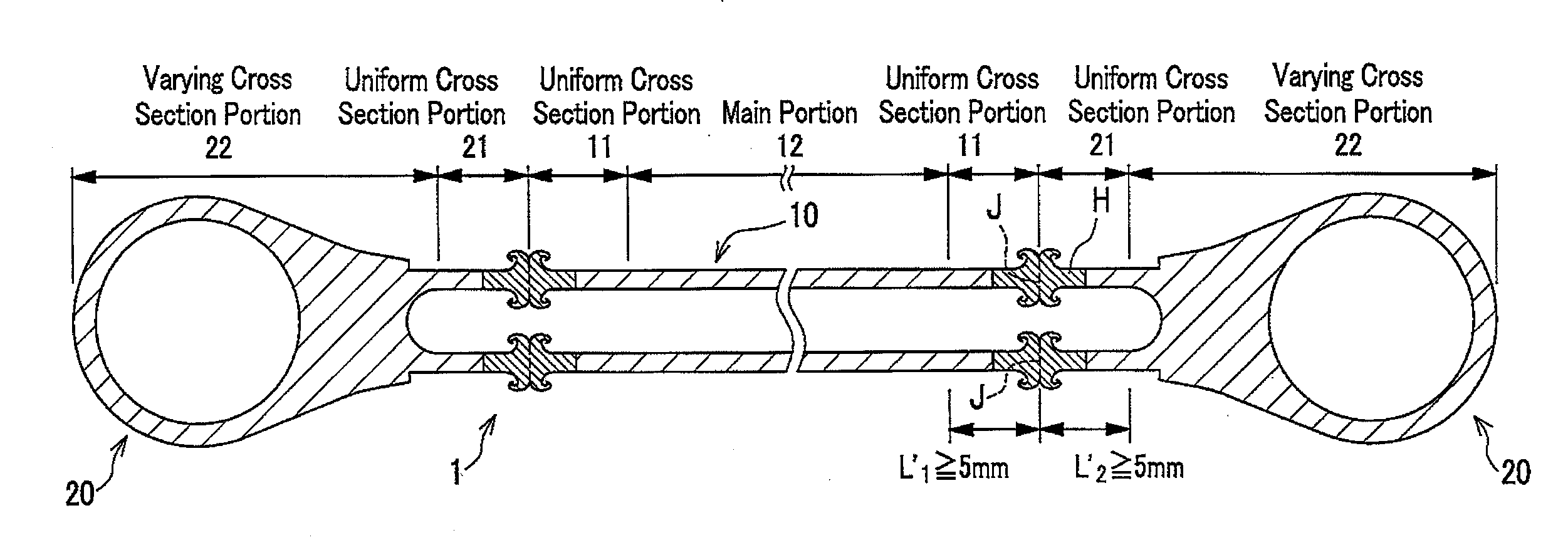
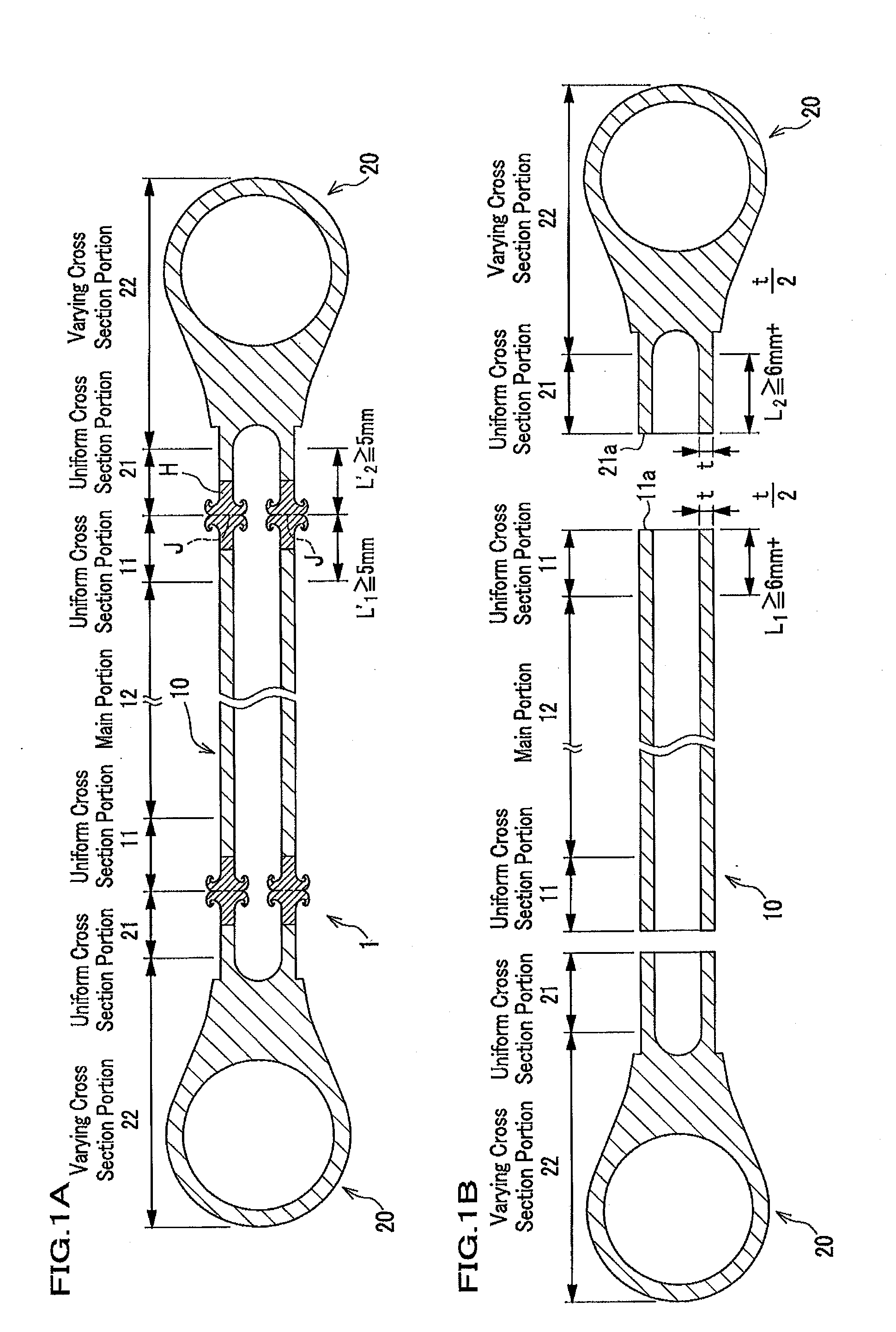
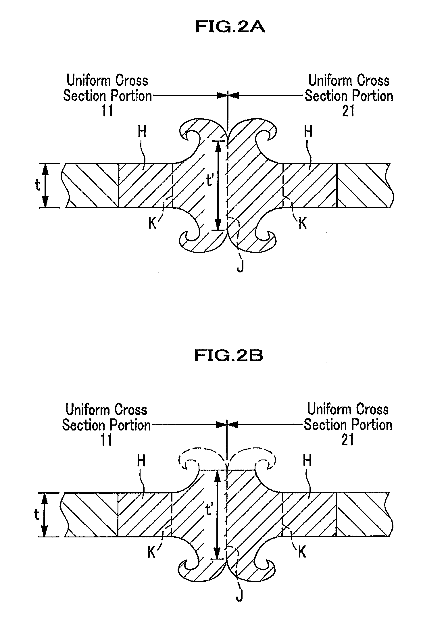
[0018]The above-mentioned friction welding allows that the HAZ caused by a friction-welding process is formed only in the uniform cross-section portions, and that oxide films already formed on the end surfaces of the uniform cross-section portions can be removed from the weld interface, resulting in a favorable joint strength with no variation.
[0019]The present invention requires no confinement regarding conformations of the first member and the second member. Note, however, that if a friction-welded part is to be used for a suspension part including a suspension rod, a pipe-shaped extrusion material can be used for the first member, while an end member formed by using an extrusion material can be used for the second member. Preferably, the uniform cross-section portion of the second member should have a cylindrical shape, and the length of the uniform cross-section portion before friction welded should be equal to or less than the outer diameter of the uniform cross-section portion. It should be noted that the uniform cross-section portion of the second member can be produced by performing cutting and drilling work on a portion of the aluminum extrusion material. By setting the length of the uniform cross-section portion of the second member before friction welded to be equal to or less than the outer diameter of the uniform cross-section portion, it can limit an increase in time and cost required for cutting and drilling work. In addition, if performed likewise, the volume of aluminum alloy removed as shavings can be minimized, avoiding materials from running to waste.
[0020]According to a friction-welded part of the present invention, it becomes much easier to design a part. In addition, according to a method of friction-welding provided by the present invention, it is possible to obtain a friction-welding part which is much easier to design.

Problems solved by technology

However, because of friction heat generated during friction welding, it is unavoidable to have a heat affected zone (hereinafter referred to as “HAZ”) at and in the vicinity of a weld interface.
If a size of HAZ is enlarged beyond a uniform cross section portion to include a part of a non-uniform cross-section portion (whose cross-sectional shape varies), it becomes difficult and complicated to design a suspension part, since stress concentration can easily occur in the non-uniform cross-section portion.
Namely, if the size of HAZ reaches the non-uniform cross-section portion, changes in stress due to variations in cross-sectional shape, as well as changes in strength caused by heat effects must be taken into account, which makes it difficult to design a suspension part.
The same problem is also encountered for a general friction-welded part formed by friction-welding a first member and a second member together.
In other words, if the length of the uniform cross-section portion of the second member before friction-welded is greater than the outer diameter of the uniform cross-section portion, it can increase time and cost required for cutting and drilling work.
In addition, the volume of aluminum alloy removed for cutting and drilling can also increase, resulting in increase in the wasted material.

Method used


Image

  • Friction-Welded Part and Method of Friction Welding
  • Friction-Welded Part and Method of Friction Welding
  • Friction-Welded Part and Method of Friction Welding

Examples


example

1. Size of HAZ

[0057]Experiments were performed in order to investigate the size of HAZ “H” to be created during a friction-welding process using a first member 10 and a second member 20. The first member 10 and the second member 20 used for the friction-welding process were made of a well-tempered Al—Mg—Si series alloy (i.e. JIS standard 6061 aluminum alloy) which had undergone the T6 treatment (i.e. the alloy material having undergone a solution treatment, quenching and then artificial ageing), and formed of an extrusion material. Specifically, the first member 10 was produced by cutting a pipe-shaped extrusion material down to a predetermined size. The second member 20 was produced first by cutting the extrusion material down to a predetermined size, followed by cutting work. In this experiment, the uniform cross-section portion 11 in the first member 10 and the uniform cross-section portion 21 in the second member 20 had a cylindrical shape and the same sectional dimension. The l...


PUM

PropertyMeasurementUnit
Timeaaaaaaaaaa
Thicknessaaaaaaaaaa
Thicknessaaaaaaaaaa

Abstract

The invention provides a friction-welded part featuring easy design as well as a method of producing said part. The friction-welded part 1 is produced by friction-welding a first member 10 and a second member 20 together. The first member 10 is made of an aluminum alloy material, having a uniform cross-section portion 11 whose cross-sectional shape and size are not changed. The second member 20 is made of an aluminum alloy material, having a uniform cross-section portion 21 whose cross-sectional shape and size are not changed. According to the invention, the uniform cross-section portions 11 and 21 are friction-welded together to form the part 1. A heat affected zone “H” caused by friction welding is formed only in the uniform cross-section portions 11 and 21. The uniform cross-section portion 11 of the first member 10, and the uniform cross-section portion 21 of the second member 20, respectively, have a cylindrical shape, preferably having the same sectional dimension.

Description

BACKGROUND OF THE INVENTION[0001]1. Field of the Invention[0002]This invention relates to friction-welded parts and a method of friction-welding.[0003]2. Description of Related Art[0004]Conventionally, an iron material is used for cylindrical parts used to constitute a suspension for an automobile, such as an upper link, a lower link, and a radius rod (hereinafter referred to as “suspension part”). However, in order to reduce a vehicle weight, an aluminum alloy material has come to be used more commonly for recent years. For example, Japanese Laid-open Patent Publication No. H11-156562 discloses a suspension part that is formed by friction pressure-welding aluminum-alloy end members onto both sides of an aluminum-alloy pipe-shaped member.[0005]Friction pressure-welding (hereinafter referred to as “friction-welding”) is one of solid-state welding methods and enables joining members of various materials with constant quality, since the friction-welding process does not leave any defec...

Claims


Application Information

Patent Timeline
IPC IPC(8): B32B1/08B32B15/01B23K20/12
CPCB23K20/121Y10T428/12292B23K20/129B60G2206/11B60G2206/82013B23K20/2336B23K2201/006B23K2203/10B23K2201/04B60G7/001Y10T428/12764B23K2101/006B23K2101/04B23K2103/10
Inventor SUMI, SHINICHIROMIZUGUCHI, KOUMOCHIZUKI, HIROYUKINAKAKURA, KAZUHIRO
Owner NIPPON LIGHT METAL CO LTD
Learn More