

3-axial accelerometer
a technology of accelerometer and axial plane, which is applied in the direction of acceleration measurement, measurement devices, instruments, etc., can solve the problems of affecting the mass to performance ratio, high price and large size, and limited accuracy
- Summary
- Abstract
- Description
- Claims
- Application Information
AI Technical Summary
Benefits of technology
Problems solved by technology
Method used
Image

Examples
first embodiment
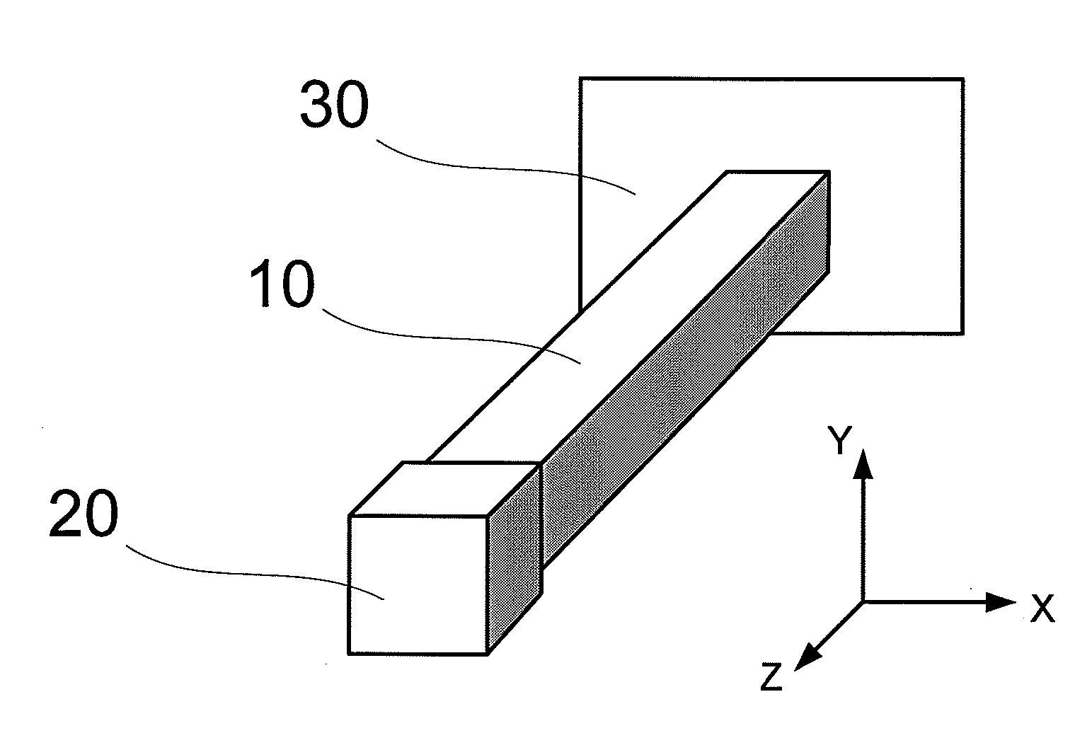
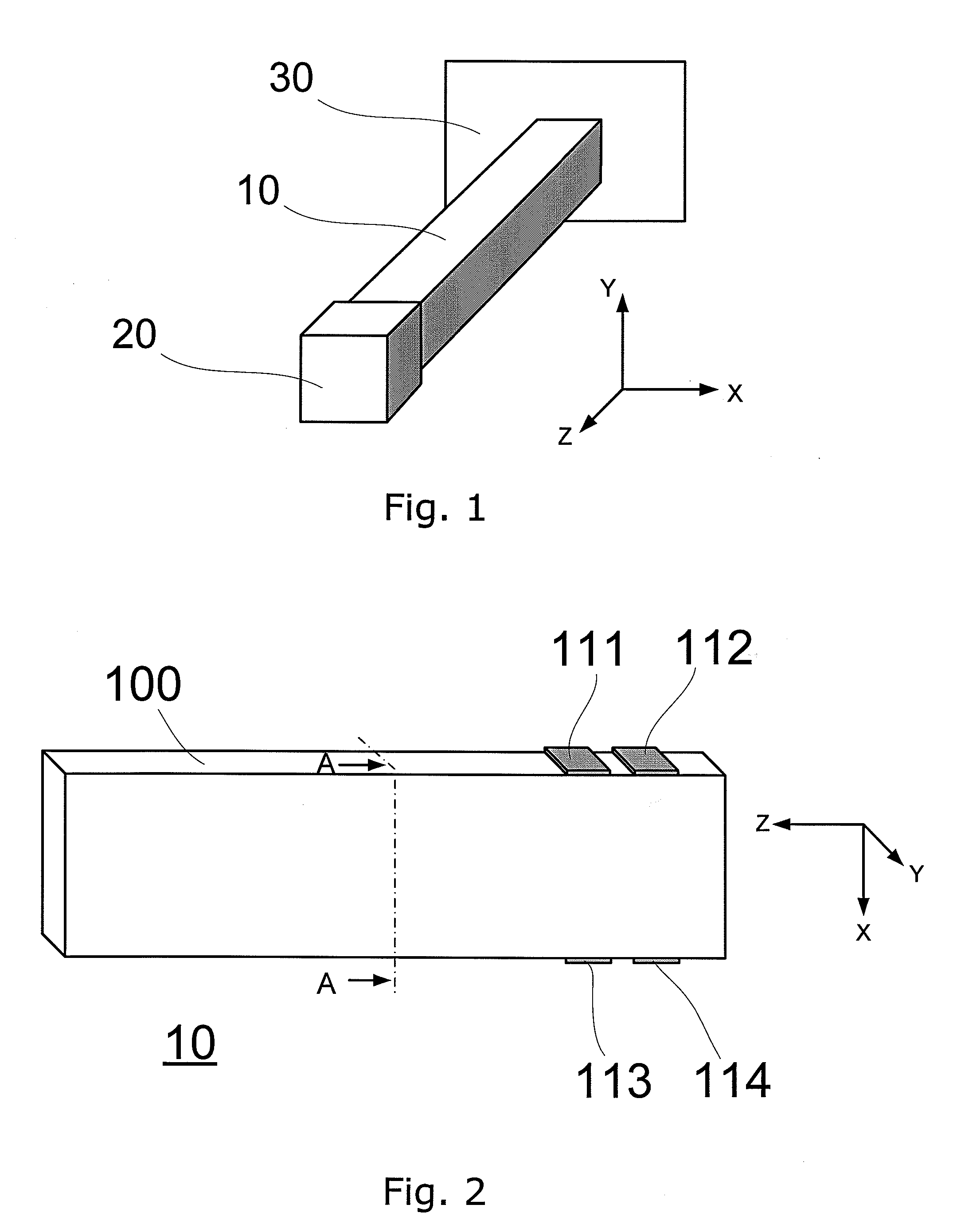
[0036]FIG. 1 illustrates a schematic isometric view of the accelerometer assembly in the invention;
[0037]FIG. 2 illustrates an isometric top view of the active body of the 3-axial piezoelectric accelerometer in the first embodiment of the invention;
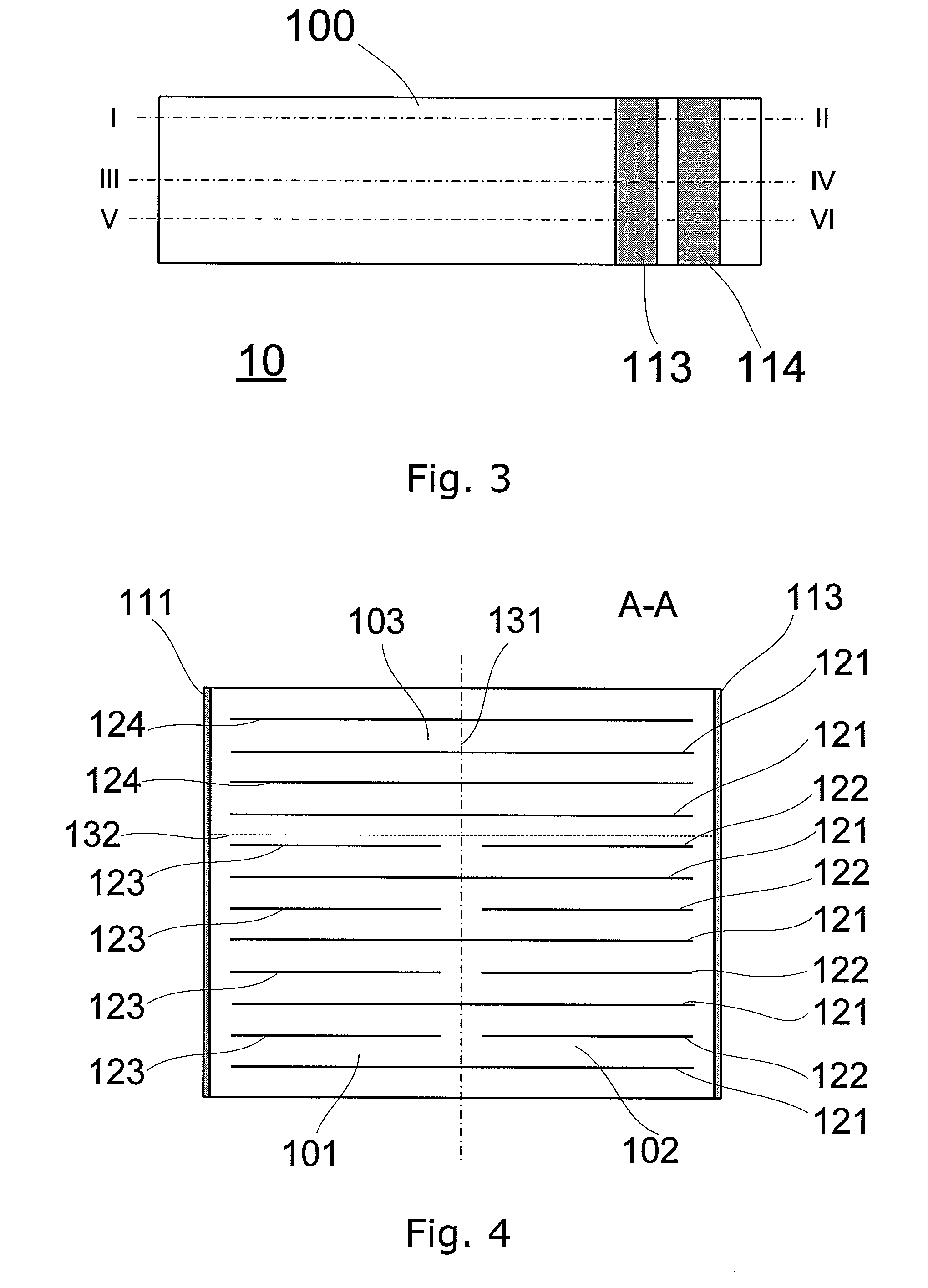
[0038]FIG. 3 illustrates a side view of the active body of the 3-axial piezoelectric accelerometer in FIG. 2;
[0039]FIG. 4 illustrates a cross-sectional view of the active body of the 3-axial piezoelectric accelerometer, taken along the line A-A on FIG. 2;
[0040]FIG. 5 illustrates a cross-sectional top view of the active body of the 3-axial piezoelectric accelerometer, taken along the line I-II on FIG. 3;
[0041]FIG. 6 illustrates a cross-sectional top view of the active body of the 3-axial piezoelectric accelerometer, taken along the line III-IV on FIG. 3;
[0042]FIG. 7 illustrates a cross-sectional top view of the active body of the 3-axial piezoelectric accelerometer, taken along the line V-VI on FIG. 3;
second embodiment
[0043]FIG. 8 illustrates an isometric top view of the active body of the 3-axial piezoelectric accelerometer in the invention in which the active body consists of four regions;
[0044]FIG. 9 illustrates a side view of the active body in the second embodiment of the invention shown in FIG. 8;
[0045]FIG. 10 illustrates a cross-sectional view of the active body in the second embodiment of the invention, taken along the line A-A on FIG. 8;
[0046]FIG. 11 illustrates a cross-sectional top view of the active body in the second embodiment of the invention, taken along the line I-II on FIG. 9;
[0047]FIG. 12 illustrates a cross-sectional top view of the active body in the second embodiment of the invention, taken along the line III-IV on FIG. 9;
[0048]FIG. 13 illustrates a cross-sectional top view of the active body in the second embodiment of the invention, taken along the line V-VI on FIG. 9;
third embodiment
[0049]FIG. 14 illustrates an isometric top view of the active body in the invention, in which the active body comprises five regions;
[0050]FIG. 15 illustrates a side view of the active body of the active body in the third embodiment of the invention, shown in FIG. 14;
[0051]FIG. 16 illustrates a cross-sectional view of the active body in the third embodiment of the invention, taken along the line A-A on FIG. 14;
[0052]FIG. 17 illustrates a cross-sectional top view of the active body in the third embodiment of the invention, taken along the line I-II on FIG. 15;
[0053]FIG. 18 illustrates a cross-sectional top view of the active body in the third embodiment of the invention, taken along the line III-IV on FIG. 15;
[0054]FIG. 19 illustrates a cross-sectional top view of the active body in the third embodiment of the invention, taken along the line V-VI on FIG. 15;
[0055]FIG. 20 illustrates a cross-sectional top view of the active body in the third embodiment of the invention, taken along th...
PUM
 Abstract
Description
Claims
Application Information