Pipette tip having carrier/fluid enclosed therein, apparatus for treating pipette tip having carrier/fluid enclosed therein and method of treating pipette tip having carrier/fluid enclosed therein

a technology of pipette and carrier, which is applied in the field of pipette tips, can solve the problems of affecting the flow rate of liquid through the pipette, affecting the efficiency of the reaction, and affecting the performance of the support, so as to improve the reaction efficiency, smooth the passage, and improve the effect of reaction efficiency

Active Publication Date: 2010-02-25
UNIVERSAL BIO RESEARCH CO LTD
View PDF8 Cites 24 Cited by
  • Summary
  • Abstract
  • Description
  • Claims
  • Application Information

AI Technical Summary

Benefits of technology

[0081]According to the first invention, the ninth invention or the seventeenth invention, the pipette tip having a support and a fluid enclosed therein in which the support and the fluid for sustainedly activating the support to be contacted with the support are enclosed in the pipette tip in advance is used by directly or indirectly attaching the pipette tip to the nozzle through which the gas is sucked or discharged by a specific control.
[0082]Therefore, the support whose activation is maintained may initiate the treatment immediately. Furthermore, since the fluid for sustainedly activating the support is enclosed in a breakable state in advance by occluding the attachment opening and the opening of the pipette tip, even gel particles are used as the support, the state in which air bubbles between the gel particles are completely removed in advance is maintained, and the liquid is smoothly passed between the gel particles, whereby the reaction efficiency may be improved. Moreover, drying of the support such as a gel is prevented, whereby deterioration of the performance of the support and the deformation or damage of the support may be prevented.
[0083]Since the flow of the liquid is not unidirectional but may be bidirectional where the amount or the surface area contacting with the liquid of the support is constant, the liquid may be contacted with the support more efficiently by repeating suction and discharging. Therefore, separation, extraction, purification performance and treatment efficiency with respect to the support may be improved.
[0084]Furthermore, the support may be contacted with the liquid by selecting any liquid existing outside and sucking it while the support is enclosed in the pipette tip. Therefore, by replacing the treatment of the support with the controls of the relative transfer between the pipette tip having a support and a fluid enclosed therein and the container provided outside, and of sucking and discharging, the treatment may be automated, diversified and made versatile.
[0085]Since the contact efficiency between the support and the liquid may be improved by using the pipette tip having a support and a fluid enclosed therein in which the support is enclosed and the sucking and discharging mechanism having the nozzles, the necessary amount of the liquid and the necessary amount of the support may be decreased and the scale of the apparatus as a whole may be suppressed. Therefore, the same efficiency as the conventional support may be obtained by using the support by a lower amount than the amount of the conventional support.
[0086]Moreover, according to the present invention, removal, reaction, washing, temperature control, separation, stirring, dispensing, clarifying, isolation, elution and extraction may be performed by only flowing-in and flowing-out the liquid and transferring the pipette tip while the support such as a filler is kept enclosed in the pipette tip. Therefore, the treatment may be performed efficiently, rapidly and readily.

Problems solved by technology

Where a useful target material is included in the materials that are flown out, there was a problem that the target material to be separated and purified is diluted since the transfer liquid is in a large amount.
For example, where a target useful protein is separated from a residual liquid from which major proteins have been removed, as in the treatment of the proteins in the blood, there was a problem that the residual liquid is diluted since a large amount of transfer liquid is flown in the column in the treatment using a conventional column, and concentration of the residual liquid is required, and thus the treatment becomes complex.
However, there were problems that where air bubbles are included between gel particles during enclosing a support such as a support for affinity chromatography in a column or a pipette tip, passage of the liquid is obstructed and unreacted parts may be generated, and thus the column or pipette tip needs to be stored in the state that the air bubbles between the gel particles are completely removed.
Furthermore, there were problems that where the gel enclosed in the column or pipette tip is dried, the volume is changed, and as a result, the performance of the column may be deteriorated since the column correlates with the reaction volume, and that cracking may occur in the gel and the gel is disabled.
Moreover, even where the gel is fixed on thread or beads, there was a problem that air bubbles may not be removed after drying, and deformation or separation may occur due to drying.
In addition, although proteins, enzymes, antibodies and the like may be solid-phased in dried state and stored, those forming a subunit such as metal proteins and flavin having a solid-phase factor had a problem that they are dissociated once they are dried and may not be reconstructed.

Method used


Image

  • Pipette tip having carrier/fluid enclosed therein, apparatus for treating pipette tip having carrier/fluid enclosed therein and method of treating pipette tip having carrier/fluid enclosed therein
  • Pipette tip having carrier/fluid enclosed therein, apparatus for treating pipette tip having carrier/fluid enclosed therein and method of treating pipette tip having carrier/fluid enclosed therein
  • Pipette tip having carrier/fluid enclosed therein, apparatus for treating pipette tip having carrier/fluid enclosed therein and method of treating pipette tip having carrier/fluid enclosed therein

Examples


first embodiment

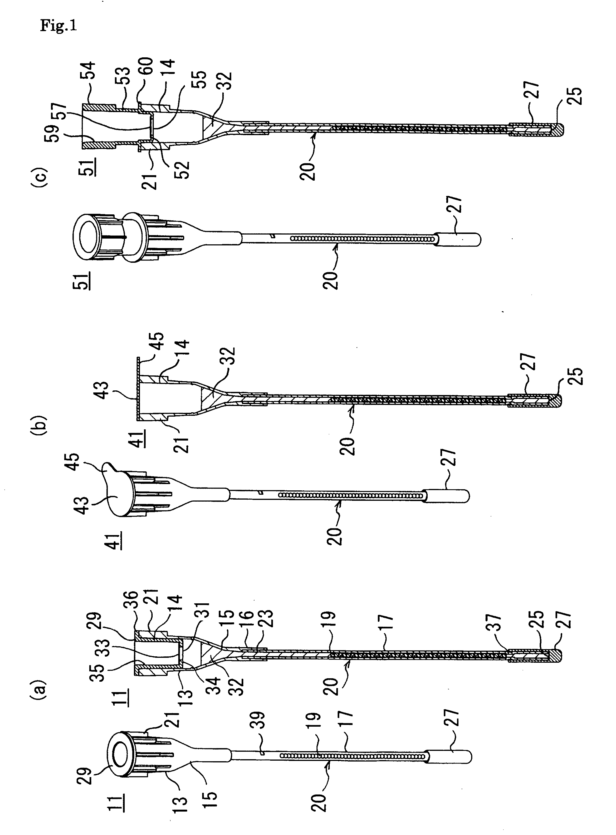
[0120]FIGS. 1 (a), (b) and (c) are drawings showing the three kinds of the pipette tips each having a support and a fluid enclosed therein 11,41 and 51 according to the present invention. In each of the pipette tips each having a support and a fluid enclosed therein 11,41 and 51, multiple particles 19 (in these cases, 43 particles) are enclosed in the pipette tip 20 as particulate supports.

[0121]Each particle 19 is labeled so as to be identified from outside by the order of alignment in an array, by various colors, or by a combination of a luminescence material or multiple luminescence materials such as various fluorescent materials and the amount ratio thereof, and each particle 19 is related to various biological materials or chemical materials fixed on the particle 19 in advance. Therefore, by identifying the particle 19 in which luminescence of the labeling material is generated by the reaction with or bond to the target biological material or the target chemical material that i...

second embodiment

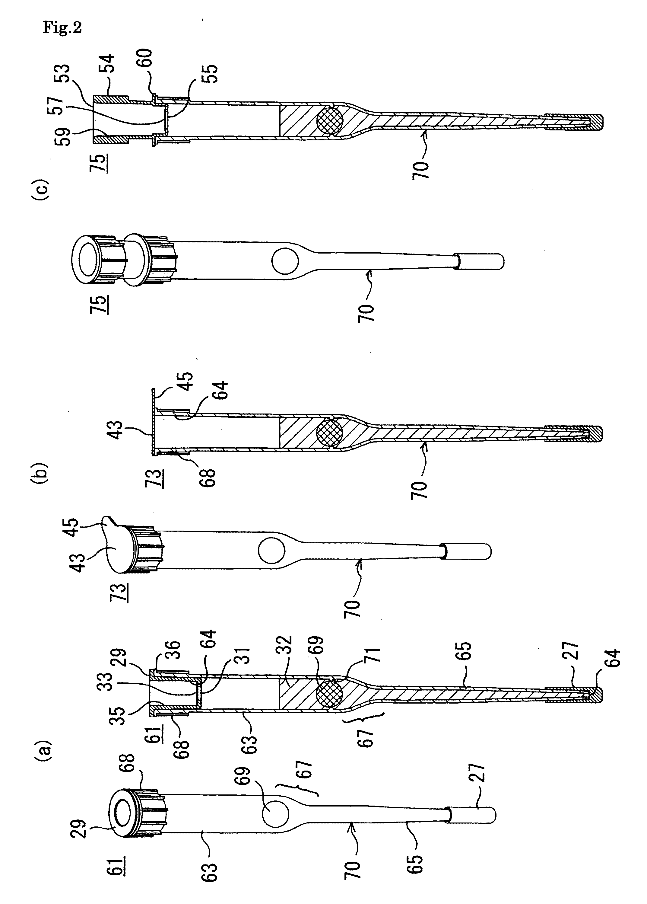
[0130]FIG. 2 is a drawing showing the three kinds of the pipette tips each having a support and a fluid enclosed therein 61, 73 and 75 according to the present invention. The symbols similar to that of FIG. 1 show similar parts, and thus the explanation thereof is not repeated here.

[0131]As shown in FIG. 2, in the pipette tips each having a support and a fluid enclosed therein 61, 73 and 75, one spherical block-shaped support 69 is enclosed in the pipette tip 70 as the support. The pipette tip 70 has the approximately cylindrical wide diameter tube 63 in which the block-shaped support 69 is enclosed, the approximately cylindrical narrow diameter tube 65 that communicates with the wide diameter tube 63 and formed narrower than the wide diameter tube 63, and the approximately funnel-shaped transition part 67 formed between the wide diameter tube 63 and the narrow diameter tube 65. The symbol 68 shows multiple protrusions provided to the upper part of the pipette tip 70 in the axial di...

third embodiment

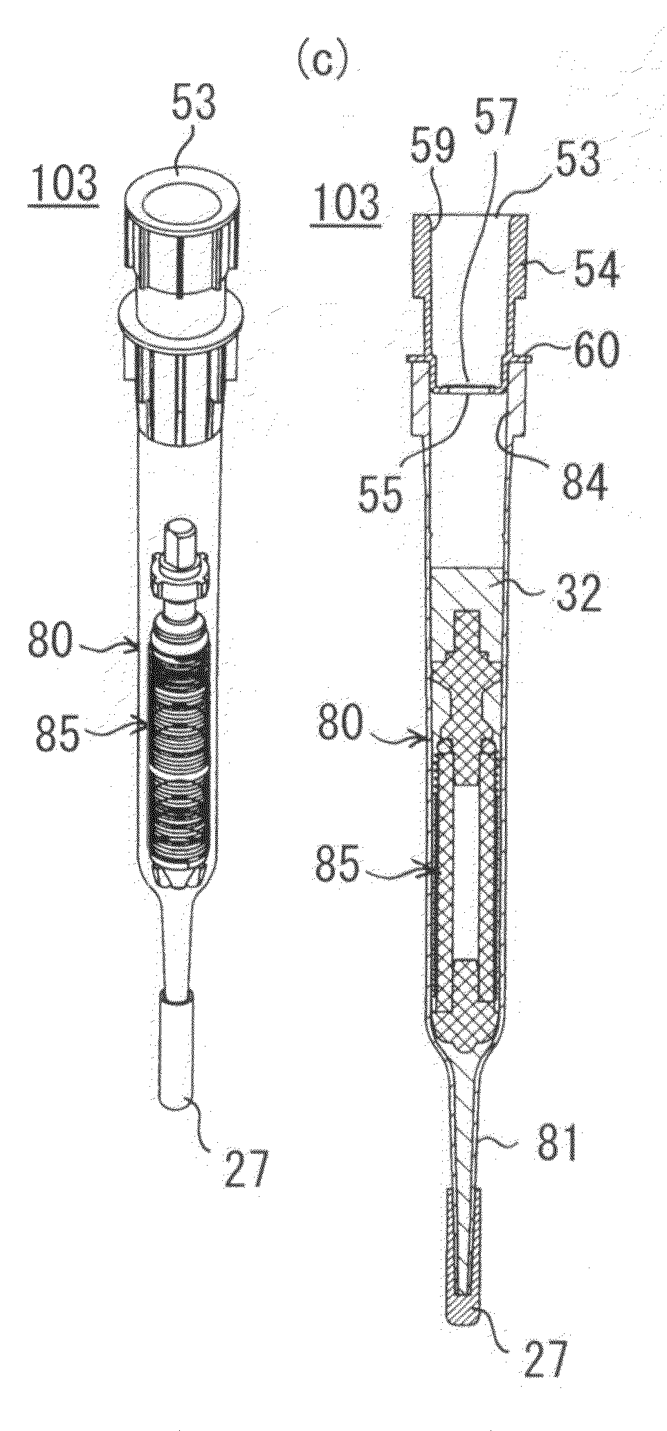
[0134]Next, FIG. 3 is a drawing showing the three kinds of the pipette tips each having a support and a fluid enclosed therein 77, 101 and 103 according to the present invention. The symbols similar to that of FIGS. 1 and 2 show similar parts, and thus the explanation thereof are not repeated here.

[0135]As shown in FIG. 3, in the pipette tips each having a support and a fluid enclosed therein 77, 101 and 103, the wound body 85 in which one rope-like support 91 as a support is wound around the cylindrical core 95 as a substrate is enclosed in the pipette tip 80. The pipette tip 80 has the approximately cylindrical wide diameter tube 79 in which the wound body 85 is enclosed, the approximately cylindrical narrow diameter tube 81 that communicates with the wide diameter tube 79 and formed narrower than the wide diameter tube 79, and the approximately funnel-shaped transition part 83 formed between the wide diameter tube 79 and the narrow diameter tube 81. The symbols 82 are multiple pr...


PUM

PropertyMeasurementUnit
particle diameteraaaaaaaaaa
volumeaaaaaaaaaa
volumeaaaaaaaaaa

Abstract

The present invention relates to a pipette tip having a support and a fluid enclosed therein, an apparatus for treating the pipette tip having a support and a fluid enclosed therein, and a method of treating the pipette tip having a support and a fluid enclosed therein. The present invention aims at providing separation and purification that may be performed more efficiently and rapidly than the treatments using a conventional treatment using liquid chromatograph or a filter, and constituted to have a function for sustainedly activating the support by comprising a pipette tip comprising an attachment opening that is to be attached to a nozzle for sucking and discharging a gas or to a connecting tube attachable to the nozzle and may be communicated with the nozzle, and an opening that allows flow-in and flow-out of a liquid in response to the suction and discharging of the gas; a support enclosed in the pipette tip, which may adsorb or capture a biological material in the liquid or react with or bond to the biological material; and a fluid for sustainedly activating the support, which comprises a predetermined liquid or a predetermined gas that is enclosed in the pipette tip in a breakable state and comes into contact with the support.

Description

TECHNICAL FIELD[0001]The present invention relates to a pipette tip having a support and a fluid enclosed therein, an apparatus for treating the pipette tip having a support and a fluid enclosed therein, and a method of treating the pipette tip having a support and a fluid enclosed therein.BACKGROUND ART[0002]Conventionally, a cylindrical container, called a column, having a liquid inlet and outlet in the center of an upper and lower circular plates, is filled with a particulate filler, called a gel, having a particle diameter of ten to several hundred microns, so that removal, separation and purification of a substance are performed utilizing the interaction between solute molecules and the gel when a liquid is made to flow from either the upper or lower liquid inlet or outlet by a pump or the like.[0003]Incidentally, treatment steps using a column requires a large amount of transfer liquid (transfer phase) since a solution comprising a target material to be separated and purified ...

Claims


Application Information

Patent Timeline
Patent Type & Authority Applications(United States)
IPC IPC(8): B01L3/02G01N1/14
CPCB01D15/3804B01J2220/64B01L3/0275B01L2200/141B01L2200/16G01N2035/1053B01L2300/044B01L2300/0636B01L2300/0681B01L2300/069G01N30/6043B01L2300/042B01L2200/0668
Inventor TAJIMA, HIDEJI
Owner UNIVERSAL BIO RESEARCH CO LTD
Why Eureka
Try Eureka