
Probe for temporarily electrically contacting a solar cell

a solar cell and temporary technology, applied in the direction of measurement leads/probes, photovoltaic monitoring, instruments, etc., can solve the problems that the described problems cannot be remedied using this device, damage to the solar cell, and the inability to temporarily contact the solar cell, so as to prevent tension

Inactive Publication Date: 2010-02-25
CASCADE MICROTECH
View PDF2 Cites 26 Cited by
  • Summary
  • Abstract
  • Description
  • Claims
  • Application Information

AI Technical Summary

Benefits of technology

[0010]A feed movement is to be understood here as the movement of the probe which is executed by the probe after production of a relative position between probe and solar cell in a direction up to the final production of the contact. It thus comprises the feed movement until reaching the reference position signaled by the reference sensor, the following continuation of this movement in the same direction until the touching of an electrode terminal by a contact element, and, in addition, the continuation of this feed movement, generally referred to as overtravel, for producing a secure contact which is independent of mechanical or thermal strains, for example. The yielding embodiment of the contact element ensures the overtravel, which is precisely executable because of the control possible using the reference sensor.
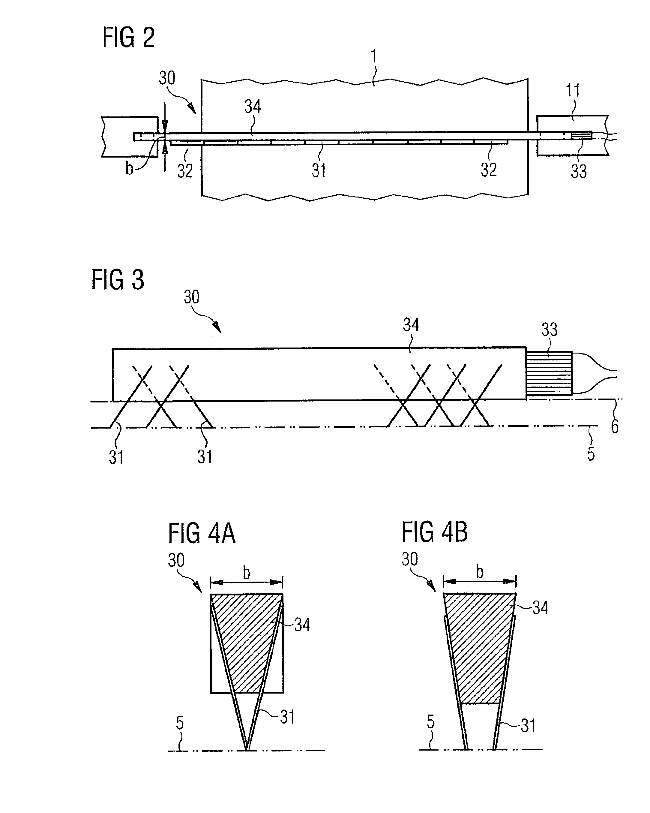
[0012]The execution of the overtravel allows a so-called “scrub” to be executed using the feed movement. To this end, the contact tips scrape over the electrode terminal because of their displacement during the overtravel and thus remove possible contaminants or passivation layers. In this way, it is possible to increase the contact reliability solely by the execution of the feed movement. A design of the contact elements as bending springs already in particular allows a scrub. If the bending springs are situated at an acute angle to the contact plane, even a slight overtravel results in sufficient scrub. In addition, the load introduced into the solar cell is minimized by the displacement of the contact elements on the electrode terminal of a solar cell in the event of such a configuration of the bending springs.
[0016]Alternatively, multiple reference sensors may also be used for the distance measurement and thus for the control of the feed movement. For example, in two-dimensionally extended probes having linearly or flatly distributed contact elements, tilting of the probe during the feed movement may be prevented by suitable numbers and positions of reference sensors, in that the reference signals generated using the individual reference sensors are used for the local differentiated movement of the probe. This is supported if a suitable mount of a probe allows the tilting thereof via one or two axes. For this purpose, a probe, which extends along an extension direction or in a plane, has a mount having two or more joints, so that the system is statically determined, i.e., the number of the reactions in these bearings is equal to the number of the degrees of freedom of the probe. This prevents tensions from occurring in the probe or in the solar cells during the contact, which may cause damage to one or both thereof.
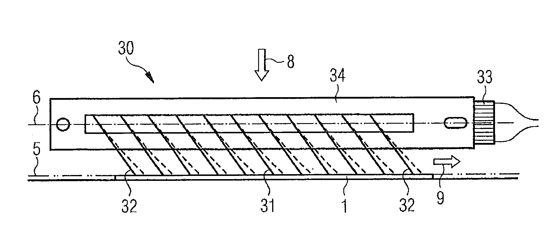
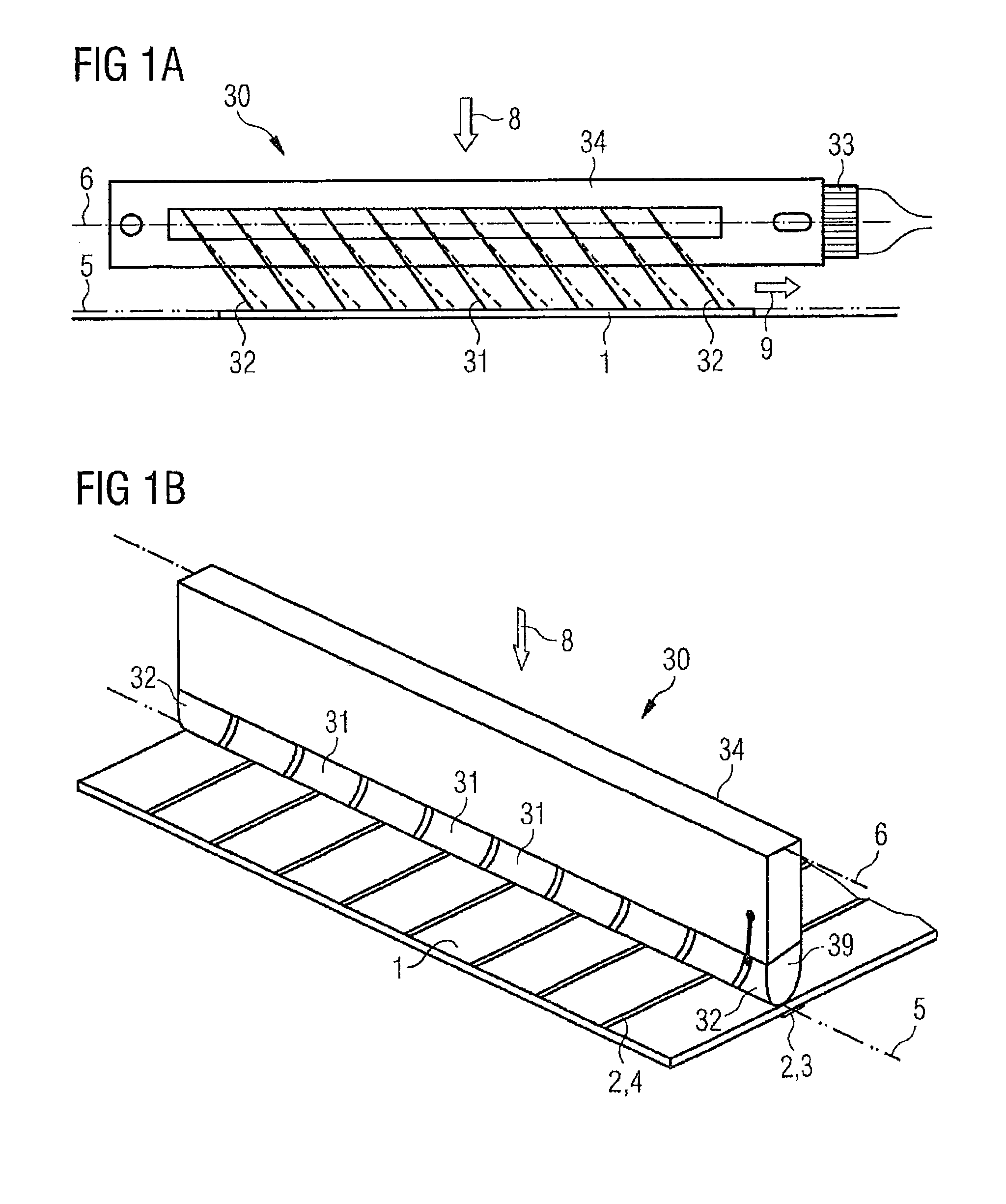
[0017]In one design, a probe has a three-fingered structure, the fingers lying so closely to one another that they may be laid adjacent to one another even on an electrode terminal surface of less than 1 mm. The middle finger of such a structure represents the contact element, while the two outer fingers are reference elements which have a defined reference potential, which does not impair the measurement, such as ground potential, applied to them to generate the reference signal. All three fingers are spring-elastic and are mounted like booms on a bracket in such a manner that their tips experience a deflection during the brief continuation of the feed movement after their contact on the electrode terminal, i.e., the overtravel, which has a directional component in the feed movement and a directional component perpendicular thereto. In this way, the “scrub” described above is possible using the feed movement, because the directional component of the deflection of the tip of the contact element which runs perpendicular to the feed movement causes the scraping of the tips over the electrode terminal.
[0019]In a comparable way, a series of contact elements may be situated adjacent to one another, which are connected in parallel for the joint placement on a high-resistance electrode terminal, such as a printed busbar. With such a linear or flat extension of the probe, in order to prevent the tilting thereof to the electrode terminal surface and thus corruption of the testing, as described above, two or more reference sensors may be situated on the probe, which may signal a uniform spacing of various points of the probe to the external reference surface and thus to the solar cell. The greatest possible spacing between the reference sensors would achieve the best leveling of the probe in this case. The reference sensors may be two fingers, which have a reference potential applied to them to generate a contact signal as the reference signal, or other suitable scanning or spacing sensors.

Problems solved by technology

In particular in the event of simultaneous contacting of multiple electric terminals of a solar cell, such high forces occur that they may cause damage to the solar cell because of mechanical loads or strains, in particular if the solar cell is only supported at points by a mount during the testing for minimal shadowing or for the possibility of two-sided contacting.
In addition, the handling of the thin and brittle solar cells, for transfer into a testing station or, in US 2007 / 0068567 A1, for positioning between two opposing probes and for removal after the testing, causes stress loads which may result in damage to the solar cell.
The latter is significant in particular for the production of solar cells in a continuous production facility, because the handling is frequently performed therein using robots, and a correction of imprinted movement sequences in the event of deviations in design and position of the solar cells, for example, is only possible in a limited way for reasons of time and cost.
The described problems also cannot be remedied using this device.

Method used


Image

  • Probe for temporarily electrically contacting a solar cell
  • Probe for temporarily electrically contacting a solar cell
  • Probe for temporarily electrically contacting a solar cell

Examples


Embodiment Construction

[0026]Various designs of solar cells may be electrically contacted for testing purposes in various manufacturing steps using the probes described hereafter, in that the configuration of the contact elements 31 is adaptable to the location and the size of the electrode terminals 2 of the solar cells 1. To test a solar cell 1, it is temporarily, i.e., only over a defined time interval of the testing, and removably contacted by probes and subjected to a light flash directed toward the front side and incident almost entirely thereon. A current generated by the light action and a voltage are tapped as the measuring signal via the probes 30 and supplied to analysis. The contacting is performed only by laying the probes 30 on the electrode terminals 2 of the solar cell 1, and the contact is interrupted by lifting the probes 30. In this way, a series of solar cells 1 can be temporarily contacted, tested, and transported further continuously.

[0027]The probe described hereafter is to be usabl...


PUM


Abstract

A probe for temporarily electrically contacting a solar cell for testing purposes, has at least one elastic, electrically conductive contact element for producing the electrical contact, at least one reference sensor for indicating a distance of the contact element to an external reference surface using an electrical signal of the reference sensor, and a mounting plane to which the tip of the contact element is oriented. The probe ensures a secure electrical contact of the solar cell in a testing station with minimal mechanical stress, and is also suitable for use in an industrial continuous production method.

Description

CROSS REFERENCE TO RELATED APPLICATIONS[0001]This application claims priority of German application no. 10 2008 038 186.1-35 filed on Aug. 19, 2008, the entire disclosure of which is hereby incorporated herein by reference.BACKGROUND ART[0002]The invention relates to a probe for temporarily electrically contacting a solar cell for testing purposes.[0003]In the course of the production of solar cells and solar modules comprising solar cells, the electrical contacting of the front and / or rear electric terminals of the solar cell is necessary for their functional testing. Both a reliable electrical contact and also the mechanical sensitivity of the solar cells are to be taken into consideration. On the one hand, the mechanical sensitivity requires a minimization of the force, using which a mechanical and thus electrical contact is produced by probes. On the other hand, a defined force is needed in order to produce the contact securely and ensure it in the course of the measurement. In ...

Claims


Application Information

Patent Timeline
IPC IPC(8): G01R1/06
CPCG01R1/07342H02S50/10H01R11/18Y02E10/50
Inventor KIESEWETTER, JORGBECKER, AXELTEICH, MICHAELDIETRICH, CLAUSWAUER, HARTMUT
Owner CASCADE MICROTECH
Learn More