
System and method for receiving high spectral efficiency optical dpsk signals

a high spectral efficiency, optical signal technology, applied in the field of optical communication, can solve problems such as additional power imbalance, and achieve the effect of optimizing the performance of signal reception and improving performan

Active Publication Date: 2010-02-25
RPX CORP
View PDF5 Cites 15 Cited by
  • Summary
  • Abstract
  • Description
  • Claims
  • Application Information

AI Technical Summary

Benefits of technology

[0006]Embodiments of the present invention can be applied, for example, to the transmission of 40-Gb / s differential binary phase shift keying (DBPSK) signals over a 50-GHz DWDM grid, as well as 100-Gb / s differential quadrature phase-shift keying (DQPSK) signals over a 50-GHz grid. Such embodiments enable 40-Gb / s DBPSK and 100-Gb / s DQPSK signals to be carried over DWDM systems having a 50-GHz minimum channel spacing with improved performance in terms of system reach and ROADM support.
[0007]Further embodiments of the present invention also provide other benefits such as adaptively optimizing the performance of the signal reception under different filtering conditions by adjusting the power ratio without changing the delay or FSR of the ODI, thereby making the signal reception hitless or free of interruption.

Problems solved by technology

Moreover, the receiver includes means for introducing an additional power imbalance between the signals corresponding to the two outputs of the ODI demodulator, wherein the additional power imbalance is related to the ratio of FSR to SR.

Method used


Image

  • System and method for receiving high spectral efficiency optical dpsk signals
  • System and method for receiving high spectral efficiency optical dpsk signals
  • System and method for receiving high spectral efficiency optical dpsk signals

Examples


Embodiment Construction

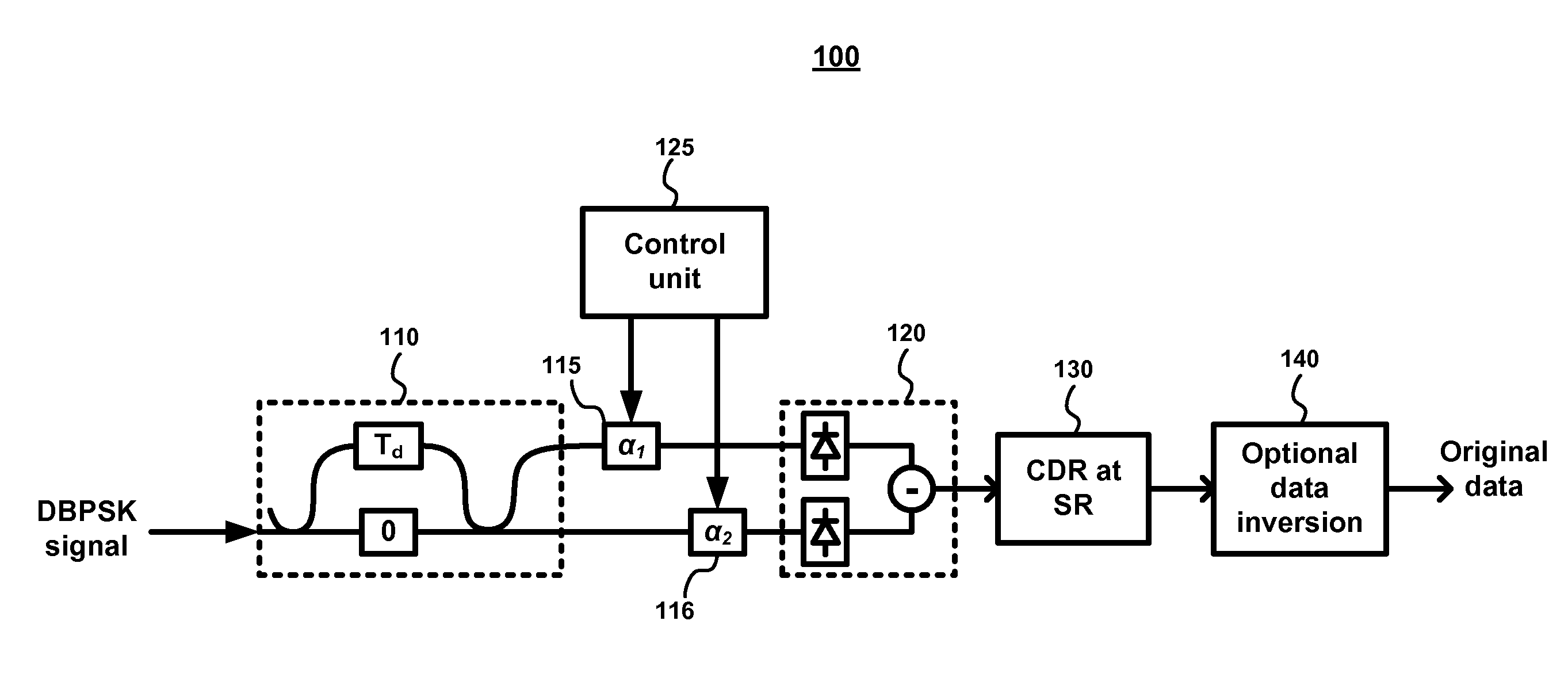
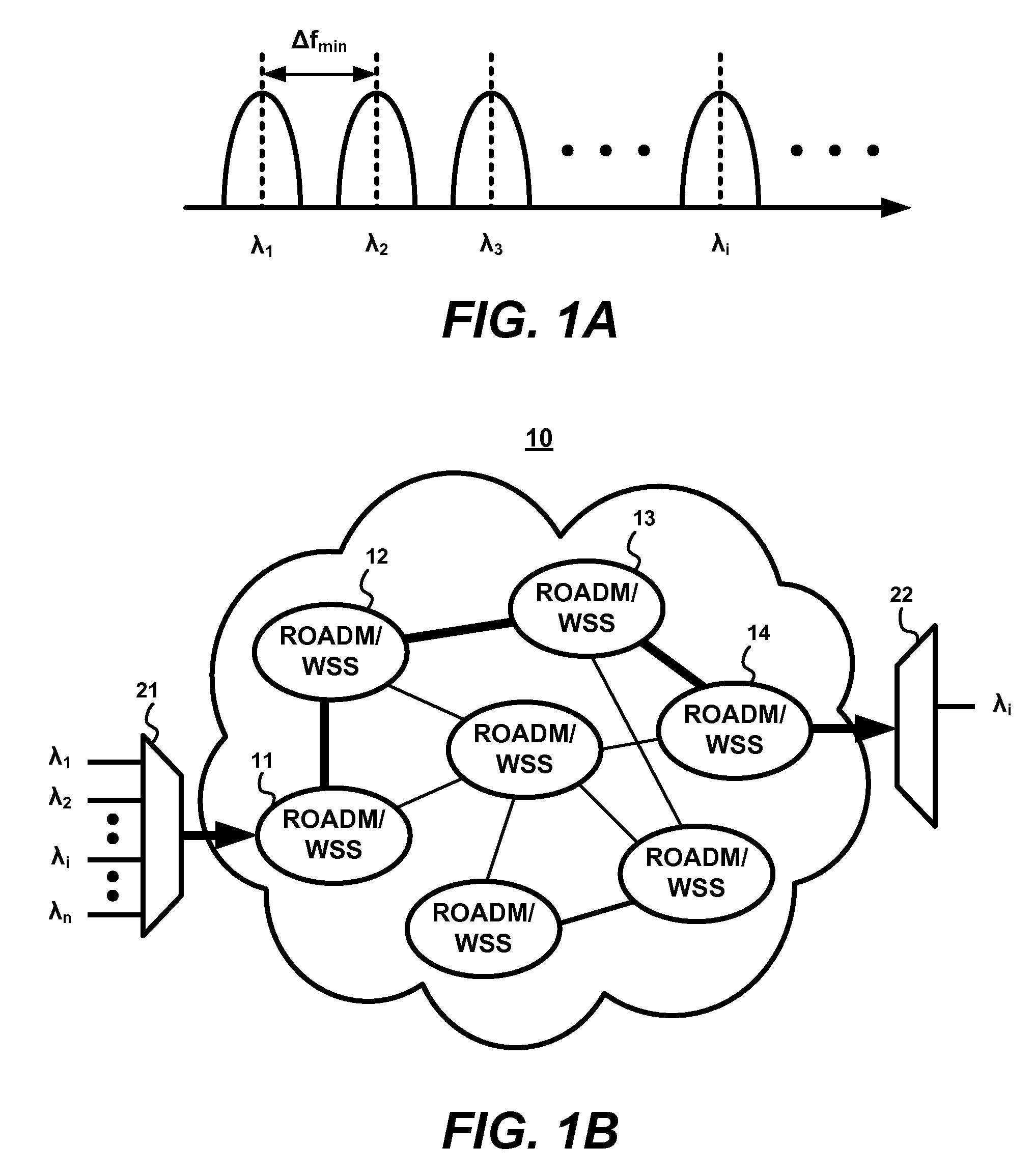
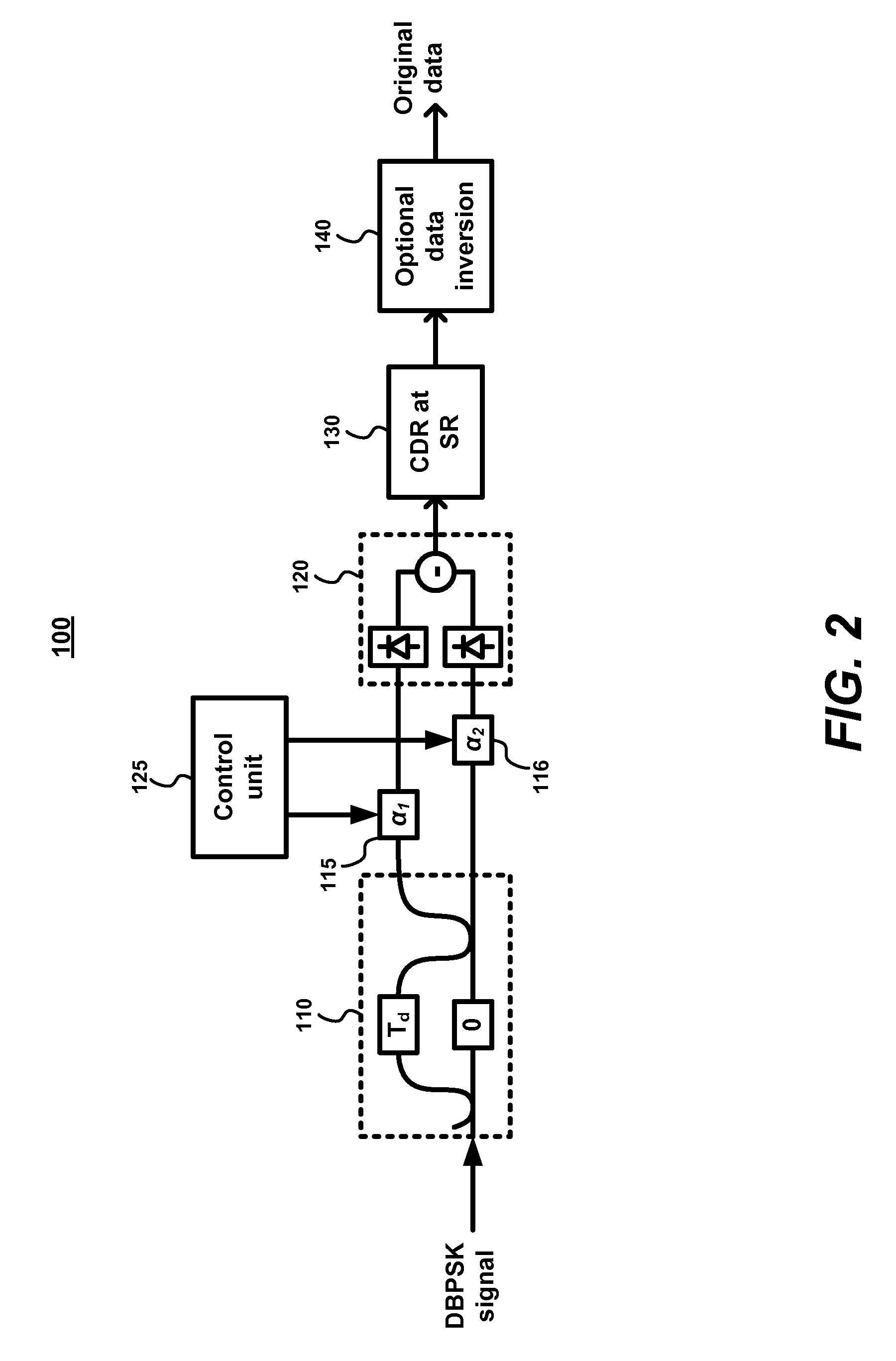
[0014]FIG. 2 is a block diagram of an exemplary embodiment of a differential binary phase shift keying (DBPSK) receiver 100 in accordance with the present invention. It is contemplated that the receiver 100 can be used, for example, to receive DBPSK signals, whose data rate is nominally 43 Gb / s and can range from about 40 Gb / s to 50 Gb / s, transmitted over a dense wavelength-division multiplexing DWDM system (FIG. 1B) with 50-GHz minimum channel spacing Δfmin=50 GHz (FIG. 1A).

[0015]The receiver 100 comprises an optical delay interferometer (ODI) 110 for demodulating a received optical DBPSK signal at its input. In general, an ODI has two optical paths with different lengths. The length difference between the two paths causes a time delay Td between the optical signals traveling along the two paths, and the delay equals the reciprocal of the free spectral range (FSR) of the ODI, i.e., FSR=1 / Td. In accordance with the present invention, the ODI 110 has an FSR that is greater than the s...


PUM


Abstract

Apparatus and methods are provided for receiving differential phase-shift keyed (DPSK) optical signals subjected to tight optical filtering, such as may be experienced by 40 Gb / s and 100 Gb / s channels in a dense wavelength division multiplexing (DWDM) communications system with 50 GHz channel spacing. An optical DPSK receiver is described which employs an optical delay interferometer (ODI) demodulator having a free spectral range (FSR) that is larger than the symbol rate (SR) of the DPSK signal to be demodulated. The receiver includes means for introducing an additional power imbalance between the outputs of the ODI demodulator, and the additional power imbalance may be related to the ratio of FSR to SR. The additional power imbalance increases the signal tolerance to tight optical filtering, thereby achieving high spectral efficiency in applications such as DWDM.

Description

FIELD OF THE INVENTION [0001]The present invention relates to the field of optical communications, and more specifically to apparatus and methods related to the reception of differential phase shift keyed optical signals transmitted with high spectral efficiency.BACKGROUND INFORMATION [0002]Optical differential phase-shift keying (DPSK) is a promising modulation format that offers high receiver sensitivity, high tolerance to major nonlinear effects in high-speed transmissions, and high tolerance to coherent crosstalk. In optical DPSK transmission, data information is conveyed by the optical phase difference between adjacent bits. Optical DPSK modulation includes differential binary phase shift keying (DBPSK), differential quadrature phase shift keying (DQPSK), and other related format variants.[0003]To increase the capacity of optical transport networks, 40-Gb / s channels are being considered to replace the 10-Gb / s channels currently carried on these networks. Most of the core transp...

Claims


Application Information

Patent Timeline
Patent Type & Authority Applications(United States)
IPC IPC(8): H04J14/02
CPCH04B10/677H04B10/60H04J14/02H04L27/18
Inventor CHRAPLYVY, ANDREW ROMANLIU, XIANGSETHUMADHAVAN, CHANDRASEKHAR
Owner RPX CORP
Learn More