Antenna System

a wireless communication network and antenna technology, applied in the field of antenna systems for wireless communications networks, can solve the problems of increased operational expenses associated with adopting multiple leased lines, high cost of high-capacity systems, and associated costs of backhaul methods, so as to reduce the power of transmitted and received interference, increase the gain of beams, and reduce the effect of transmission and receiving interference signal power

Inactive Publication Date: 2010-02-25
QUEENS UNIV OF BELFAST +2
View PDF3 Cites 13 Cited by
  • Summary
  • Abstract
  • Description
  • Claims
  • Application Information

AI Technical Summary

Benefits of technology

[0016]Preferably, the radiation pattern of the first antenna is narrower in azimuth than that of the second antenna. A narrower beam is beneficial since this increases the gain of the beam and reduces the transmitted and received interference signal power. A stronger ratio of signal to noise and interference received in the link between base stations enables a higher data rate so that a smaller share of the available timeslots is required for the link between the first and second base stations. It is feasible that the first antenna can have a narrower beam in azimuth than the second antenna, since the first antenna receives signals only from the second base station—which is fixed in location—whereas the second antenna has to receive signals from user equipments, which are mobile and can potentially be present in any part of the sector of the second antenna.
[0017]Conveniently, the first or second antenna system is selected for connection to a transceiver by a radio frequency switch; this has the benefit that a single radio transceiver and feeder cable can be shared between transceiving signals in the first and second timeslots.
[0018]Preferably, the control of the radio frequency switch is by means of the detection of a power characteristic at the output of the transceiver and by means of decoding of a message representing the switching point with respect to the power characteristic; this advantageously removes the need for a dedicated control cable between the transceiver and the switch and thus reduces the costs of the transceiving system.
[0019]In one arrangement, the first antenna system comprises an antenna array and the second antenna system comprises a subset of the antenna array; this has the advantage of minimising the size of the combination of the first and the second antenna systems.
[0020]Conveniently, the first and second antenna systems are implemented by applying alternative amplitude and phase weighting values to a multi-element beamformer. On reception, a multi-element beamformer receives signals from an array of antenna elements and modifies the amplitude and phase characteristic of the signal from each antenna element and combines the signals to form a single output. On transmission, a multi-element beamformer receives a single input signal, splits the signal into multiple components, and modifies the amplitude and phase characteristics of each signal transmitted to each antenna element. This has the benefit that the antenna pattern of the array of antenna elements can be controlled by the application of weighting values in a programmable manner without physical modification to the antenna array.

Problems solved by technology

Consequently, the operational expense associated with adopting multiple leased lines has also increased, making this a potentially expensive option for high capacity systems.
However each of these methods of backhaul has associated costs.
Dedicated fibre links can be expensive in terms of capital expense due mainly to the cost of the civil works in installation, and this problem is especially acute in urban areas.
Microwave links also involve the capital expense of equipment and require expert installation due to narrow beam widths leading to the requirement for precise alignment of antennas.
So it can be seen that the base station antennas are not designed to give even coverage over 360 degrees from an individual base station.
As a result, this antenna arrangement may not be ideal for communication with a relay node 3 outside the normal area of coverage of the base station 1, as, depending on its location, the relay node may fall in a null between the lobes in the tri-cellular radiation pattern and in addition the down-tilt of the antennas may reduce gain beyond a certain distance from the base station.
There may be a significant reduction in capacity available in the access links to the user equipment due to the need to reserve timeslots for backhaul.
Hence it can be seen that backhaul links for high capacity cellular wireless systems can present a significant expense; to mitigate this, the cellular wireless resource can be used to relay backhaul links from one base station to another, but when employed in conventional arrangements, this incurs significant limitations to data capacity and restrictions on the positioning of base stations.

Method used


Image

  • Antenna System
  • Antenna System
  • Antenna System

Examples


Embodiment Construction

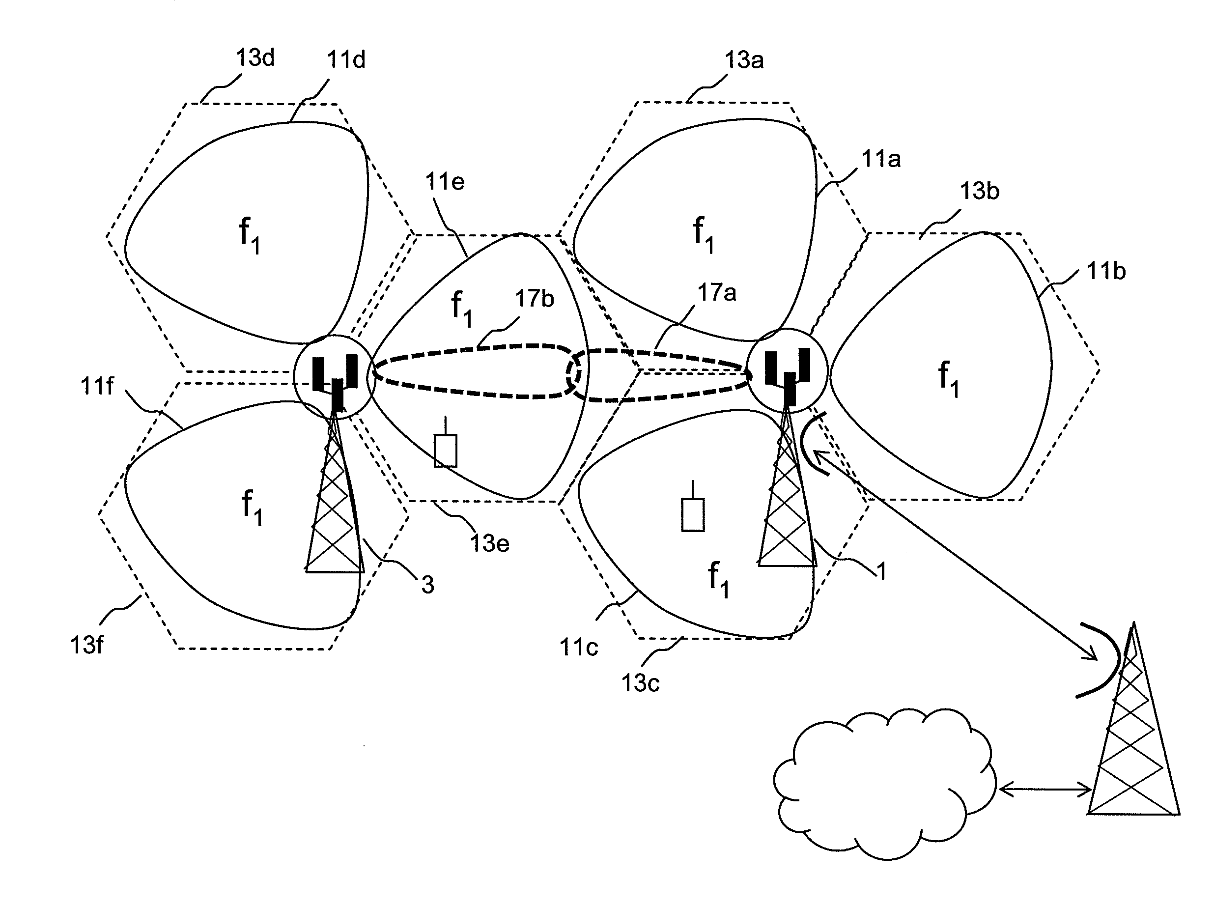
[0033]In general, the present invention is directed to methods and apparatus that provide backhaul by using the cellular wireless resource within a cellular wireless system. For clarity, the methods and apparatus are described in the context of a high speed packet data system such as IEEE802.16 (WiMax) or LTE, but it will be appreciated that this is by way of example and that the methods and apparatus described are not limited to this example.

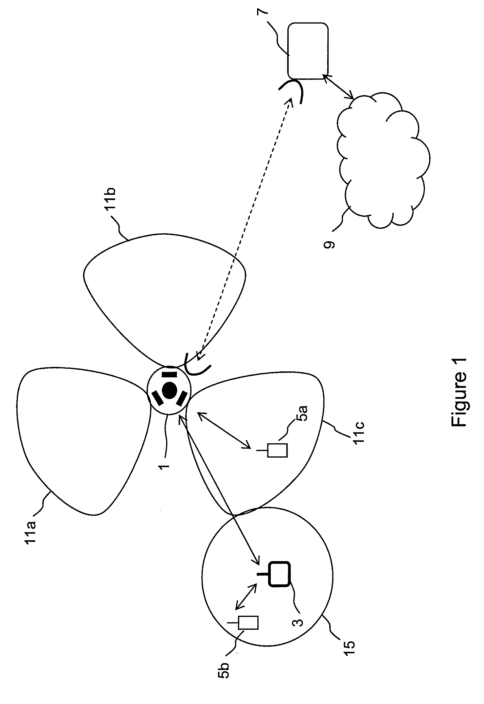
[0034]FIG. 3 shows a first embodiment of the invention. As in the case of conventional arrangements, a user equipment 5b is in communication with a relay node base station 3, the relay node producing an omnidirectional radiation pattern 15. Backhaul from the relay node 3 is provided by a link 18 to a base station 1 which itself has a microwave link to a microwave station 7 and thence to a telecommunications network 9. In the system illustrated in FIG. 1, the backhaul link 18 from the relay node 3 to the base station 1 is via lobe 11a of the rad...


PUM


Abstract

Embodiments of the invention relate to wireless communications networks, and more specifically to an antenna apparatus for cellular wireless systems. Increasing data capacity of cellular wireless systems places increasing demands on the capacity of the two way connection, known as backhaul, between a cellular base station and a telecommunications network such as the PSTN backhaul, since this is the connection that has to convey the wireless-originating traffic to its destination, often in an entirely different network. Known backhaul links include leased lines, microwave links, optical fibre links or radio resources for relaying backhaul traffic between base stations. The fixed line solutions are expensive to implement and maintain, while the radio solutions antenna configurations that are not ideal for relaying data between base stations. In embodiments of the invention, communication between base stations occurs in a first timeslot by use of a first antenna system and communication between a given base station and a user equipment occurs in a second timeslot using a second antenna system. The benefit of this method is that the first antenna system can be optimised for use in communication between base stations, whereas the second antenna system can be optimised for communication with user equipment which preferably occurs within the area of cellular wireless coverage of the sector served by the second antenna system.

Description

FIELD OF THE INVENTION [0001]The present invention relates generally to antenna systems for wireless communications networks, and more specifically to a method and antenna apparatus relating to wireless backhaul for cellular wireless systems.BACKGROUND OF THE INVENTION [0002]Mobile telephony systems, in which user equipment such as mobile handsets communicate via wireless links to a network of base stations connected to a telecommunications network, have undergone rapid development through a number of generations. The initial deployment of systems using analogue modulation has been be superseded by second generation digital systems, which are themselves currently being superseded by third generation digital systems such as UMTS and CDMA. Third generation standards provide for a greater throughput of data than is provided by second generation systems; this trend is continued with the proposal by the Third Generation Partnership Project of the so-called Long Term Evolution system, oft...

Claims


Application Information

Patent Timeline
Patent Type & Authority Applications(United States)
IPC IPC(8): H04W72/04H04W48/16H04W74/04H04W84/04H04W92/20
CPCH01Q1/246H04W48/16H04W74/04H04W88/06H04W92/20H04W88/10H04B1/0064H04W84/042
Inventor GALE, SIMONURQUHART, ANDREW
Owner QUEENS UNIV OF BELFAST
Why Eureka
Try Eureka