Voltage controlled oscillator, mmic, and high frequency wireless device

a voltage control and wireless technology, applied in the direction of oscillator, pulse automatic control, electrical equipment, etc., can solve the problems of low phase noise characteristics, affecting the accuracy of measuring distances or communication errors, and difficulty in making a resonator having a high q value in the vco having an output frequency above 30 ghz, etc., to achieve low phase noise characteristics and low phase noise characteristics

Inactive Publication Date: 2010-03-04
MITSUBISHI ELECTRIC CORP
View PDF5 Cites 211 Cited by
  • Summary
  • Abstract
  • Description
  • Claims
  • Application Information

AI Technical Summary

Benefits of technology

[0012]The present invention has been created as a solution to the above-mentioned problem, and it is an object thereof to obtain a voltage controlled oscillator (VCO), a monolithic microwave integrated circuit (MMIC), and a high frequency wireless device that can realize low phase noise characteristics even at an output frequency in the microwave band (1 GHz or more) or the millimeter wave band (30 GHz or more).
[0013]The present invention provides a voltage controlled oscillator including: a variable resonator; and at least one open-end stub connected in parallel to the variable resonator, the at least one open-end stub having a length smaller than or equal to an odd multiple of one quarter of a wavelength of a harmonic signal plus one sixteenth of the wavelength of the harmonic signal and larger than or equal to an odd multiple of one quarter of the wavelength of the harmonic signal minus one sixteenth of the wavelength of the harmonic signal.
[0014]The present invention also provides a voltage controlled oscillator including: a variable resonator; and at least one short-end stub connected in parallel to the variable resonator, the at least one short-end stub having a length smaller than or equal to an integral multiple of a wavelength of a harmonic signal plus one sixteenth of the wavelength of the harmonic signal and larger than or equal to an in

Problems solved by technology

When the high frequency wireless device is used for a radar device or a communication device, the phase noise affects its accuracy in measuring distances or its communication error rate.
Although many methods for controlling the phase noise are proposed as described above, it is difficult to make a resonator having a high Q value in the VCO having an output frequency above 30 GHz.
Therefore, it is impossible to obtain sufficiently low phase noise characteristics.
It is possible to use the VCO that delivers a signal of a frequency lower than the frequency handled by the wireless device together with a frequency multiplier, but it is not advantageous f

Method used


Image

  • Voltage controlled oscillator, mmic, and high frequency wireless device
  • Voltage controlled oscillator, mmic, and high frequency wireless device
  • Voltage controlled oscillator, mmic, and high frequency wireless device

Examples


embodiment 1

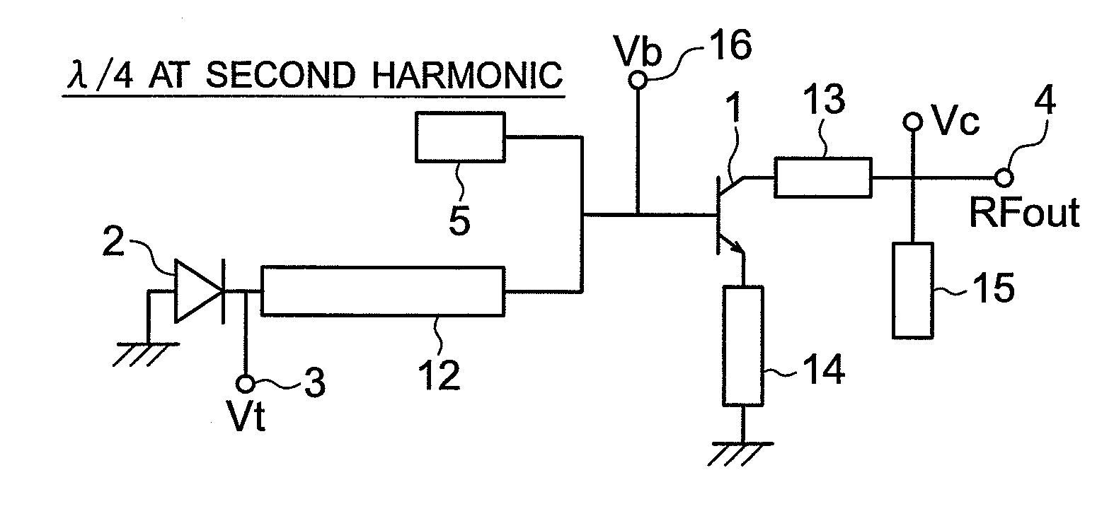
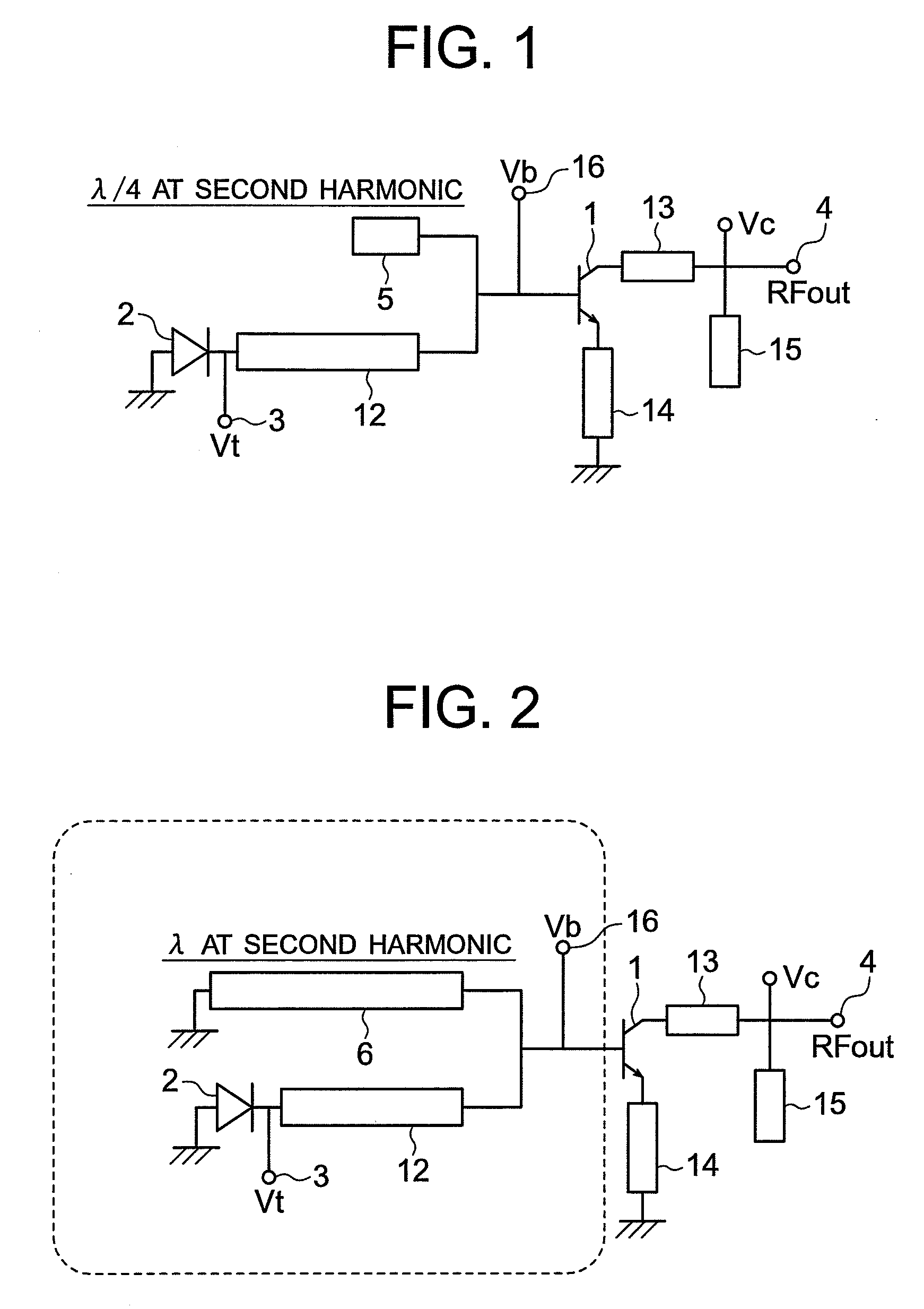
[0029]FIG. 1 is a structural diagram illustrating a structure of a VCO according to Embodiment 1 of the present invention. FIG. 1 illustrates a VCO having a serial positive feedback structure, which is a harmonic extraction oscillator in which an electric signal having a frequency that is an integral fraction of a desired frequency (i.e., fundamental wave signal) is oscillated so that a harmonic signal is delivered from an output terminal. Reference numeral 1 denotes a transistor; 2, a varactor; 3, a control voltage terminal; 4, a signal output terminal; 5, an open-end stub having a length corresponding to one quarter of the wavelength of the second harmonic signal; 12 and 13, lines; 14, an emitter line; 15, a fundamental wave reflection stub; and 16, a bias voltage terminal. The varactor 2, the line 12, and the control voltage terminal 3 constitute a variable resonator made up of a voltage variable capacitance component of the varactor 2 and an inductance component of the line 12. ...

embodiment 2

[0042]FIG. 2 is a diagram illustrating a structure of a VCO according to Embodiment 2 of the present invention. In FIG. 2, reference numerals 1 to 4 and 12 to 16 denote the same elements as those of FIG. 1, and reference numeral 6 denotes an short-end stub having a length corresponding to the wavelength of a second harmonic signal. The stub that has the short circuit load for the second harmonic frequency and is connected to the variable resonator in parallel can be realized by using the short-end stub, too. It may have the line length defined by Expression (2) below (integral multiple of the wavelength of the second harmonic signal) for the wavelength λ of the second harmonic signal.

nλ(n=1, 2, . . . )  (2)

[0043]The short-end stub 6 having the line length defined by Expression (2) becomes a short circuit load also for the fundamental wave frequency at a low frequency lower than approximately 1 GHz. Therefore, the fundamental wave signal cannot propagate to the variable resonator inc...

embodiment 3

[0053]FIG. 6 is a diagram illustrating a structure of a VCO according to Embodiment 3 of the present invention. In FIG. 6, reference numerals 1 to 4 and 12 to 15 denote the same elements as those of FIG. 1, and reference numeral 7 denotes a bias circuit having a line length from the connection node to the short circuit portion for a high frequency via a capacitor 11 corresponding to the wavelength of the second harmonic signal.

[0054]The same effect as that of Embodiment 2 in which the short-end stub is added can be obtained by letting the bias circuit make a short circuit via the capacitor 11 at the portion separated from the connection node by a distance satisfying Expression (2), without newly adding the short-end stub 6 as described above in Embodiment 2.

[0055]Although the line length of the bias circuit 7 is adapted to be a length corresponding to the wavelength of the second harmonic signal according to the above-mentioned description, this structure is not a limitation. It is ...


PUM


Abstract

A voltage controlled oscillator having low phase noise and including: a variable resonator including a varactor and a control voltage terminal; and an open-end stub connected in parallel to the variable resonator, the open-end stub having a length shorter than or equal to an odd multiple of one quarter of a wavelength of a harmonic signal plus one sixteenth of the wavelength of the harmonic signal, and longer than or equal to an odd multiple of one quarter of the wavelength of the harmonic signal minus one sixteenth of the wavelength of the harmonic signal. In this structure, a high Q value is realized for a fundamental wave frequency. Fluctuation in a control voltage due to a harmonic signal is controlled.

Description

BACKGROUND OF THE INVENTION[0001]1. Field of the Invention[0002]The present invention relates to a voltage controlled oscillator, an MMIC, and a high frequency wireless device. In particular, the present invention relates to a voltage controlled oscillator, an MMIC, and a high frequency wireless device that work in a microwave or millimeter wave range.[0003]2. Description of the Related Art[0004]In conjunction with the widespread proliferation of high frequency wireless devices including a car-mounted radar device and a mobile phone, there has been a growing requirement for high performance of oscillators having output frequency of 1 GHz or higher. The oscillator is a circuit for generating oscillation of a high frequency electric signal inside the circuit so as to deliver the high frequency electric signal to the outside. In particular, an oscillator having a control voltage terminal for changing the output frequency is called a voltage controlled oscillator (VCO). The oscillator i...

Claims


Application Information

Patent Timeline
IPC IPC(8): H03L7/00
CPCH03L7/099H03B5/1847
Inventor WATANABE, SHINSUKEGOTO, SEIKITSUKAHARA, YOSHIHIROKANAYA, KO
Owner MITSUBISHI ELECTRIC CORP
Why Eureka
Try Eureka