High frequency second harmonic oscillator

a second harmonic oscillator and high frequency technology, applied in the direction of oscillator, pulse generator, pulse technique, etc., can solve the problems of increasing the cost, the phase noise of the oscillator affecting the distance measurement accuracy or communication error rate, so as to achieve the effect of low phase noise characteristics of the oscillator and increase in phase nois

Inactive Publication Date: 2011-07-21
MITSUBISHI ELECTRIC CORP
View PDF12 Cites 0 Cited by
  • Summary
  • Abstract
  • Description
  • Claims
  • Application Information

AI Technical Summary

Benefits of technology

[0016]The present invention has been made to solve the above problems. It is, therefore, an object of the present invention to provide a high frequency second harmonic oscillator having a construction that ensures low phase noise characteristics of the oscillator by eliminating all possible causes of increase in the phase noise.

Problems solved by technology

The reason for this is that the use of a frequency multiplier complicates the construction of the wireless device and hence increases its cost, although the oscillator is allowed to generate a signal of a lower frequency than the frequency used within the device.
When an oscillator is used as a radar or communication device, the phase noise of the oscillator affects the distance measuring accuracy or communication error rate.
However, increasing the Q value makes it difficult to vary the output frequency of the oscillator even if the oscillator is provided with variable output frequency capability.
Therefore, the construction of reference literature 1 does not sufficiently reduce the phase noise of an oscillator if the phase noise is primarily caused by the 1 / f noise signal in the oscillator.
First, it has only a slight effect in reducing the phase noise.
Secondly, adding a feedback circuit to an existing oscillator results in a change in the oscillating frequency of the oscillator or prevents oscillation of the oscillator, making it necessary to redesign the oscillator.
Thus, the construction of the oscillator described in reference literature 2 also does not sufficiently reduce the phase noise.

Method used


Image

  • High frequency second harmonic oscillator
  • High frequency second harmonic oscillator
  • High frequency second harmonic oscillator

Examples


first embodiment

[0033]A first embodiment of the present invention will be described with reference to FIGS. 1 to 8. It should be noted that throughout the description of the first embodiment, certain of the same materials and the same or corresponding components are designated by the same reference numerals and described only once. This also applies to other embodiments of the invention subsequently described.

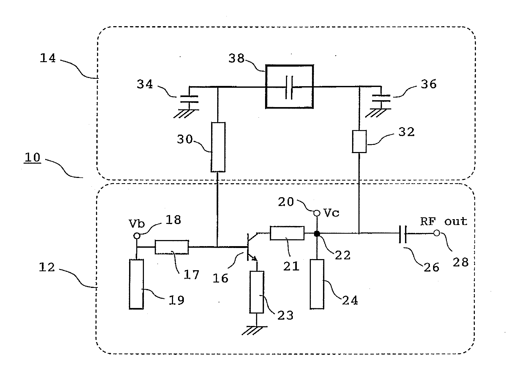
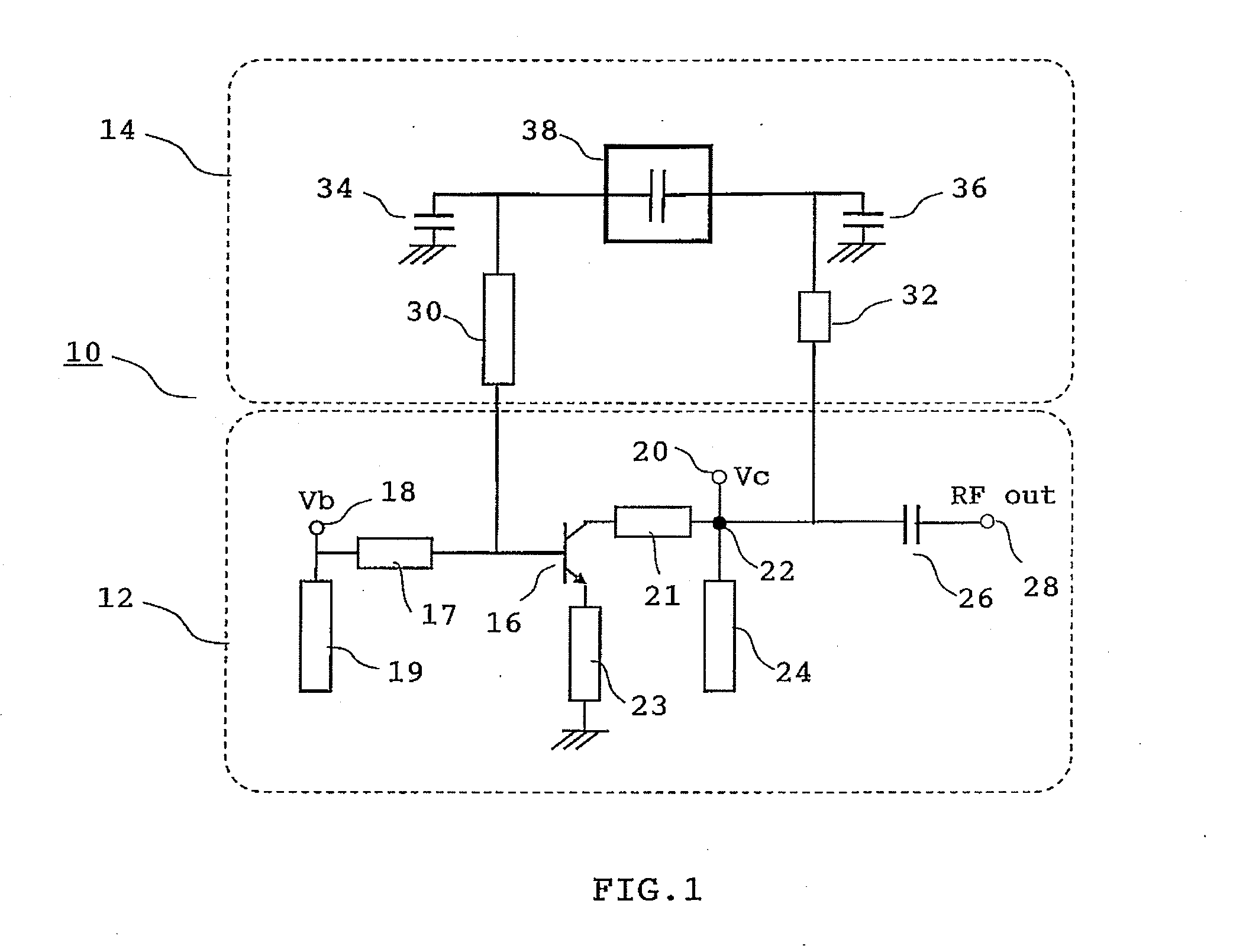
[0034]FIG. 1 is a circuit diagram illustrating the construction of a high frequency second harmonic oscillator 10 of the present embodiment. This high frequency second harmonic oscillator 10 has a series feedback configuration and includes an oscillating circuit 12 and a feedback circuit 14. The following description will be directed to the constructions of the oscillating circuit 12 and the feedback circuit 14.

[0035]The oscillating circuit 12 includes a transistor 16. The transistor 16 is a bipolar transistor made of indium gallium arsenide. A bias terminal 18 and an open stub 19 are connecte...

second embodiment

[0052]A second embodiment of the present invention will be described with reference to FIG. 9. The high frequency second harmonic oscillator of the present embodiment differs from that of the first embodiment in that it includes a resistance 50 connected in series with the high capacitance capacitor 38, which characterizes the present embodiment. It will be noted that, without the resistance 50, oscillation may occur at an undesired frequency in the loop formed by the transistor 16, the second electrical signal line 32, the high capacitance capacitor 38, and the first electrical signal line 30. The resistance 50 connected in series with the high capacitance capacitor 38 functions to suppress such unwanted oscillation. It should be noted that if the value of the resistance 50 is too high, it will also reduce the 1 / f noise feedback function. Therefore, the value of the resistance 50 must be determined by taking this into account. Further, the resistance 50 may be replaced by a variabl...

third embodiment

[0053]A third embodiment of the present invention will be described with reference to FIG. 10. The high frequency second harmonic oscillator of the present embodiment differs from that of the second embodiment in that the resistance 50 described above is replaced by an inductance 52 connected in series with the high capacitance capacitor 38, which characterizes the present embodiment. The inductance 52 connected in series with the high capacitance capacitor 38 does not reduce the 1 / f noise feedback function as much as the resistance 50 in the second embodiment, ensuring the suppression of unwanted oscillation signals in the loop described above.


PUM


Abstract

A high frequency second harmonic oscillator includes a transistor, a first signal line connected at a first end to the base or gate of the transistor, a first shunt capacitor connected at a first end to a second end of the first signal line and at a second end to ground, a second signal line connected at a first end to the collector or drain of the transistor, a second shunt capacitor connected at a first end to a second end of the second signal line and at a second end to ground, and a high capacitance capacitor connected between the first signal line and the second signal line. The first signal line has a length equal to an odd integer multiple of one quarter of the wavelength of a fundamental signal, plus or minus one-sixteenth of the wavelength of the fundamental signal.

Description

BACKGROUND OF THE INVENTION[0001]1. Field of the Invention[0002]The present invention relates primarily to high frequency second harmonic oscillators operating with microwaves or millimeter waves.[0003]2. Background Art[0004]The widespread use of high frequency wireless devices such as in-vehicle radar and cellular phones has increased the demand for higher performance oscillators having an output frequency of over 1 GHz. An oscillator is a circuit that internally oscillates to generate and output a high frequency electrical signal. Oscillators incorporate an active device such as a transistor to amplify the generated high frequency electrical signal.[0005]An oscillator which outputs a signal of the same frequency as the oscillating frequency is referred to as a “fundamental oscillator.” On the other hand, an oscillator which outputs a signal of a frequency twice the oscillating frequency is referred to as a “second harmonic oscillator.” Second harmonic oscillators have an advantage...

Claims


Application Information

Patent Timeline
Patent Type & Authority Applications(United States)
IPC IPC(8): H03B5/12
CPCH03D2200/0086H03B5/1847
Inventor WATANABE, SHINSUKETSUKAHARA, YOSHIHIROKANAYA, KOMIWA, SHINICHI
Owner MITSUBISHI ELECTRIC CORP
Why Eureka
Try Eureka