High density helicon plasma source for wide ribbon ion beam generation

a plasma source and wide ribbon technology, applied in the direction of plasma technique, ion beam tubes, coatings, etc., can solve the problems of ineffective use of helicon plasma sources as industrial ion sources, low efficiency, and inability to perform small implants, etc., to achieve the effect of improving the uniformity of extracted ion beams

Active Publication Date: 2010-03-04
VARIAN SEMICON EQUIP ASSOC INC
View PDF7 Cites 34 Cited by
  • Summary
  • Abstract
  • Description
  • Claims
  • Application Information

AI Technical Summary

Benefits of technology

[0011]In a further embodiment, a multicusp magnetic field surrounding the diffus

Problems solved by technology

While these thermal plasma sources are effective in generating the desired ions, they are typically only used to create atomic ions, due to the high temperatures developed within the arc chamber.
However, due to their heavier mass, shallow implants can be performed.
While this discharge is useful in the generation of molecular ions, its efficiency is often less than desired since the plasma density is ≦1011 cm−3, which is about one to two orders of magnitude less than arc discharge.
However, the experiments showed that Landa

Method used


Image

  • High density helicon plasma source for wide ribbon ion beam generation
  • High density helicon plasma source for wide ribbon ion beam generation
  • High density helicon plasma source for wide ribbon ion beam generation

Examples


first embodiment

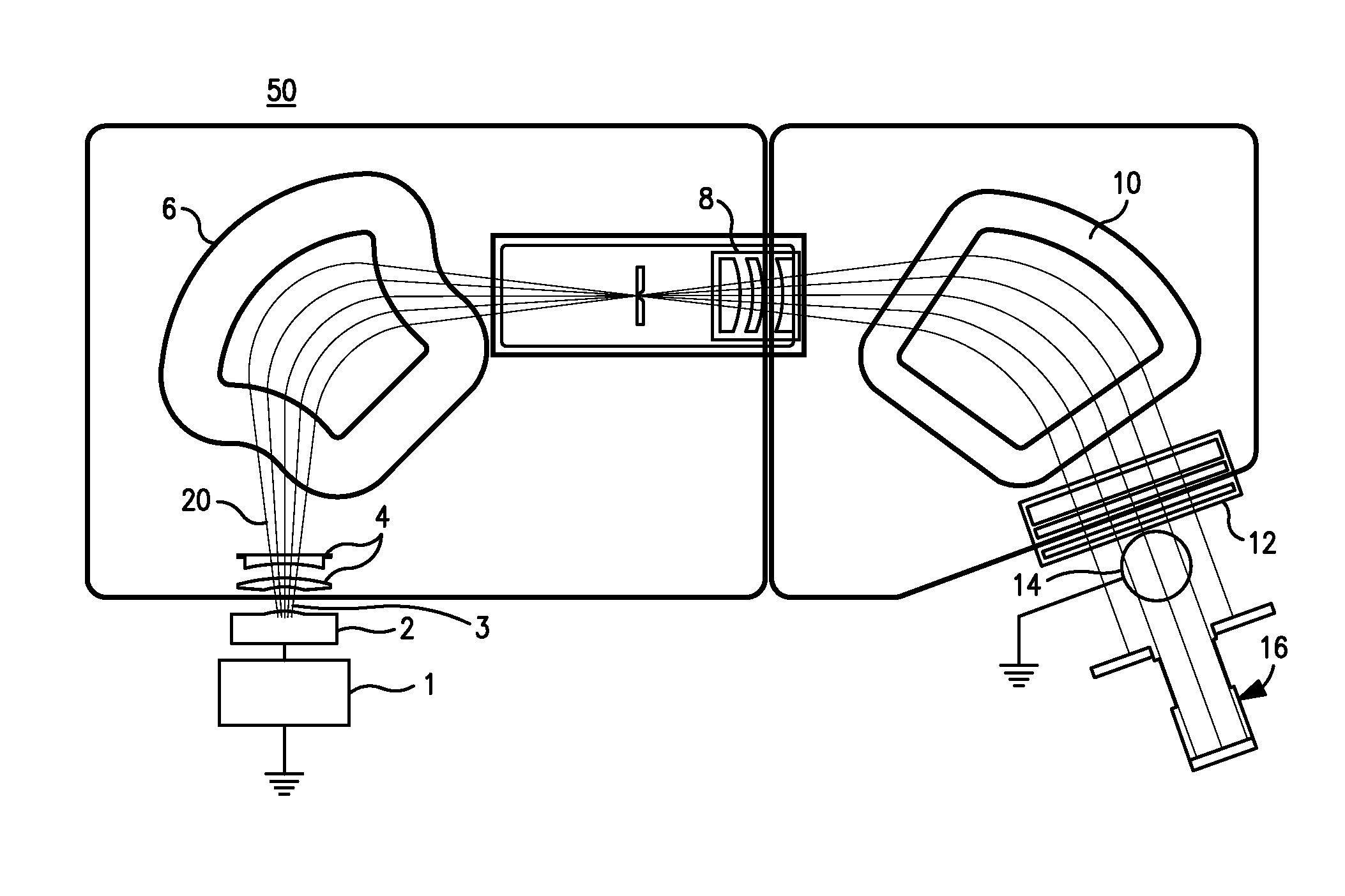
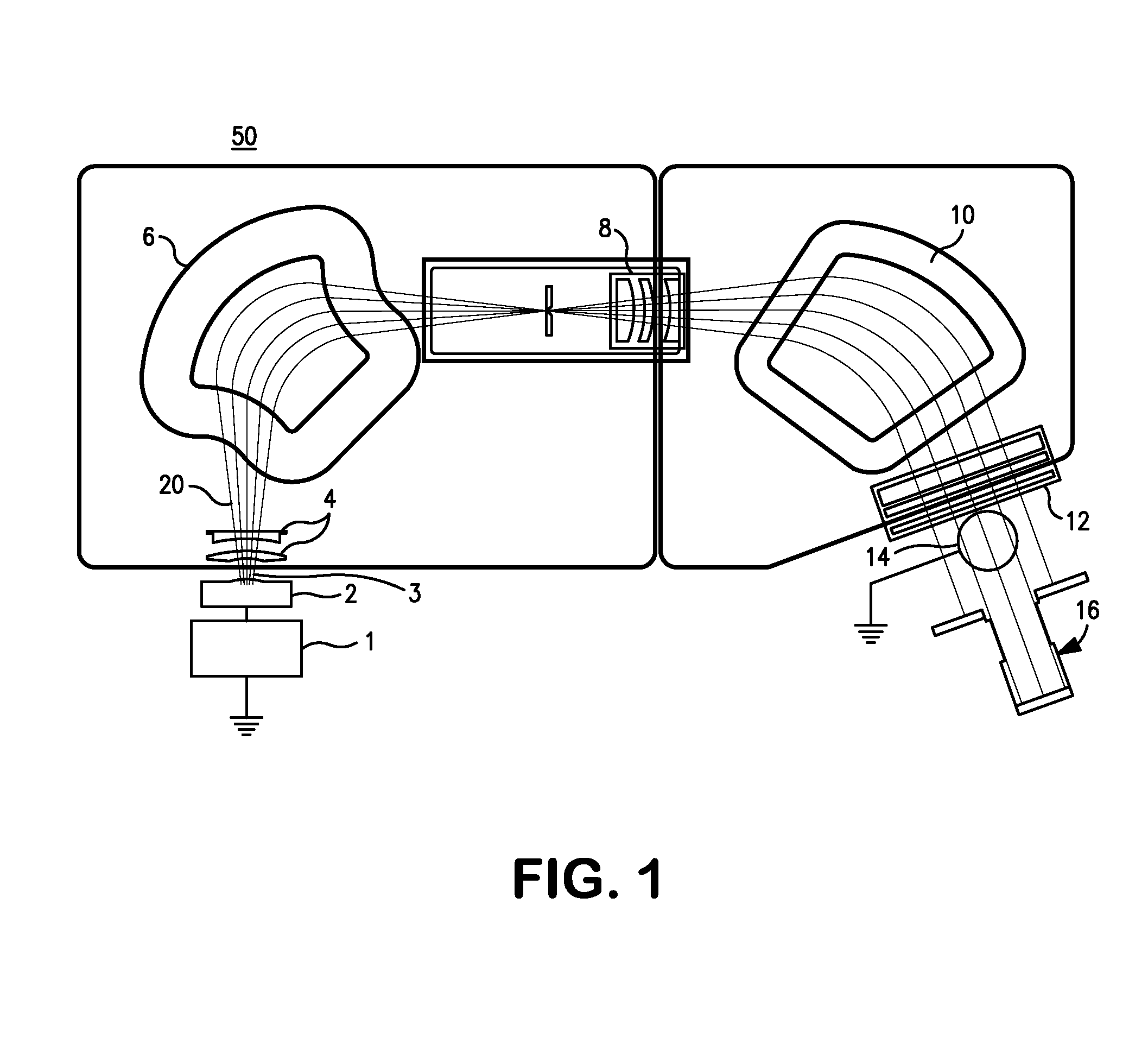
[0046]FIGS. 5a and 5b illustrate the ion source 200. Two helicon plasma sources 100, 300 such as those described in conjunction with FIGS. 3 and 4, are axially mated with a diffusion chamber 210. The diffusion chamber 210 is preferably in the shape of a cylinder, preferably having a diameter greater than that of the dielectric cylinders 110, such as 20-50 cm. The helicon sources and the diffusion chamber are aligned such that the central axis of all three components are collinear; in other words the three components are coaxial. The extraction aperture 230 is located on the diffusion chamber, parallel to the central axis of the chamber. The height of the extraction aperture is preferably small, such as 3-5 mm. The length of the diffusion chamber can be chosen to accommodate ribbon ion beam extraction slit having width of 35 cm, which will allow implantation of 300 mm diameter wafers. Because there are not limiting conditions on the length of the diffusion chamber, a wider extraction...

second embodiment

[0048]To allow extraction of positive ions, the chamber is electrically biased at positive potential by a high voltage DC power supply (not shown). In one embodiment, shown in FIG. 5b, a single extraction aperture is used to extract the beam with the help of extraction optics 250. Typically, the extraction optics 250 comprises a set of electrodes of various electrical potentials, which serve to extract the positive ions from the plasma 260. FIG. 5b shows a triode extraction optics, but thetrode or pentode assemblies can be used as well. In one embodiment, this aperture is 3 mm in height and 350 mm in length, although other sizes and configurations are possible. In a second embodiment, shown in FIG. 5c, multiple parallel apertures are used allowing for extraction of multiple beamlets 275 that further are composed and result in a taller and higher current ribbon ion beam 270.

[0049]To improve the uniformity of the plasma 260, a multicusp magnetic configuration, preferably realized with...


PUM

PropertyMeasurementUnit
Poweraaaaaaaaaa
Magnetic fieldaaaaaaaaaa
Densityaaaaaaaaaa

Abstract

An ion source, capable of generating high density wide ribbon ion beam, utilizing one or more helicon plasma sources is disclosed. In addition to the helicon plasma source(s), the ion source also includes a diffusion chamber. The diffusion chamber has an extraction aperture oriented along the same axis as the dielectric cylinder of the helicon plasma source. In one embodiment, dual helicon plasma sources, located on opposing ends of the diffusion chamber are used to create a more uniform extracted ion beam. In a further embodiment, a multicusp magnetic field is used to further improve the uniformity of the extracted ion beam.

Description

BACKGROUND OF THE INVENTION[0001]Ion implanters are commonly used in the production of integrated circuits (IC) and flat panels displays to create in a semiconductor wafer, usually silicon, regions of different conductivity by p- or n-type doping. In such devices, a plasma source is used to ionize the dopant gas. A beam of positive ions is extracted from the source, accelerated to the desired energy, mass filtered and then directed toward the wafer. As the ions strike the wafer, they penetrate to a certain depth (depending on their kinetic energy and mass) and create regions of different electrical conductivity (depending on the dopant element concentration) into the wafer. The n- or p-doping nature of these regions, along with their geometrical configuration on the wafer, define their functionality, e.g., n-p-n or p-n-p junctions within the transistors. Through interconnection of many such doped regions, the wafers can be transformed into complex integrated circuits.[0002]A block d...

Claims


Application Information

Patent Timeline
IPC IPC(8): H05H1/24C23C16/503
CPCH01J27/18H01J37/08H01J37/3171H05H1/46H01L21/26513H01L21/67005H01J2237/0817H01J37/317H01L21/265H01L21/306H05H1/34
Inventor BILOIU, COSTELPEREL, ALEXANDERSCHEUER, JAY
Owner VARIAN SEMICON EQUIP ASSOC INC
Why Eureka
Try Eureka