Bump array device having asymmetric gaps for segregation of particles

a particle segregation and array device technology, applied in the field of particles segregation, can solve the problems of limiting the practical usefulness of the fabricated device, clogging of particles too large, and limited accuracy with which small features can be fabricated in all microfabrication methods

Active Publication Date: 2010-03-11
THE TRUSTEES FOR PRINCETON UNIV
View PDF16 Cites 73 Cited by
  • Summary
  • Abstract
  • Description
  • Claims
  • Application Information

AI Technical Summary

Benefits of technology

[0013]The devices described herein can be filled with fluid and coupled with one or more fluid handling apparatus for

Problems solved by technology

The accuracy with which small features can be fabricated is limited in all microfabrication methods, especially as feature size decreases.
The strength and rigidity of materials in which small features of fabricated can also limit the practical usefulness of the fabricated device.
Furthermore, the small size

Method used


Image

  • Bump array device having asymmetric gaps for segregation of particles
  • Bump array device having asymmetric gaps for segregation of particles
  • Bump array device having asymmetric gaps for segregation of particles

Examples


example 1

A Deterministic Microfluidic Ratchet

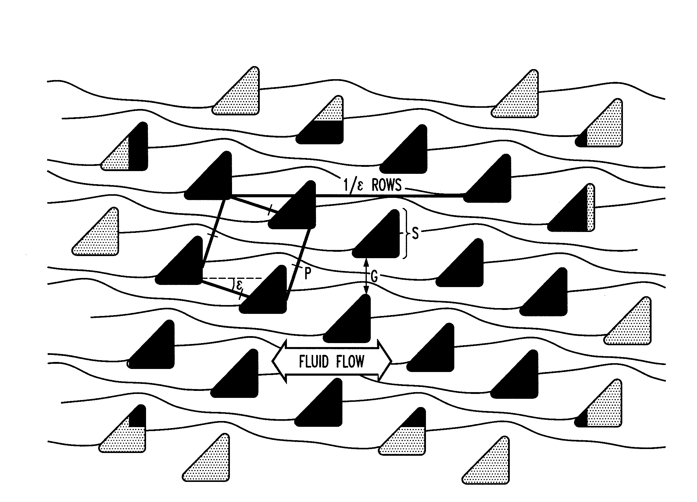
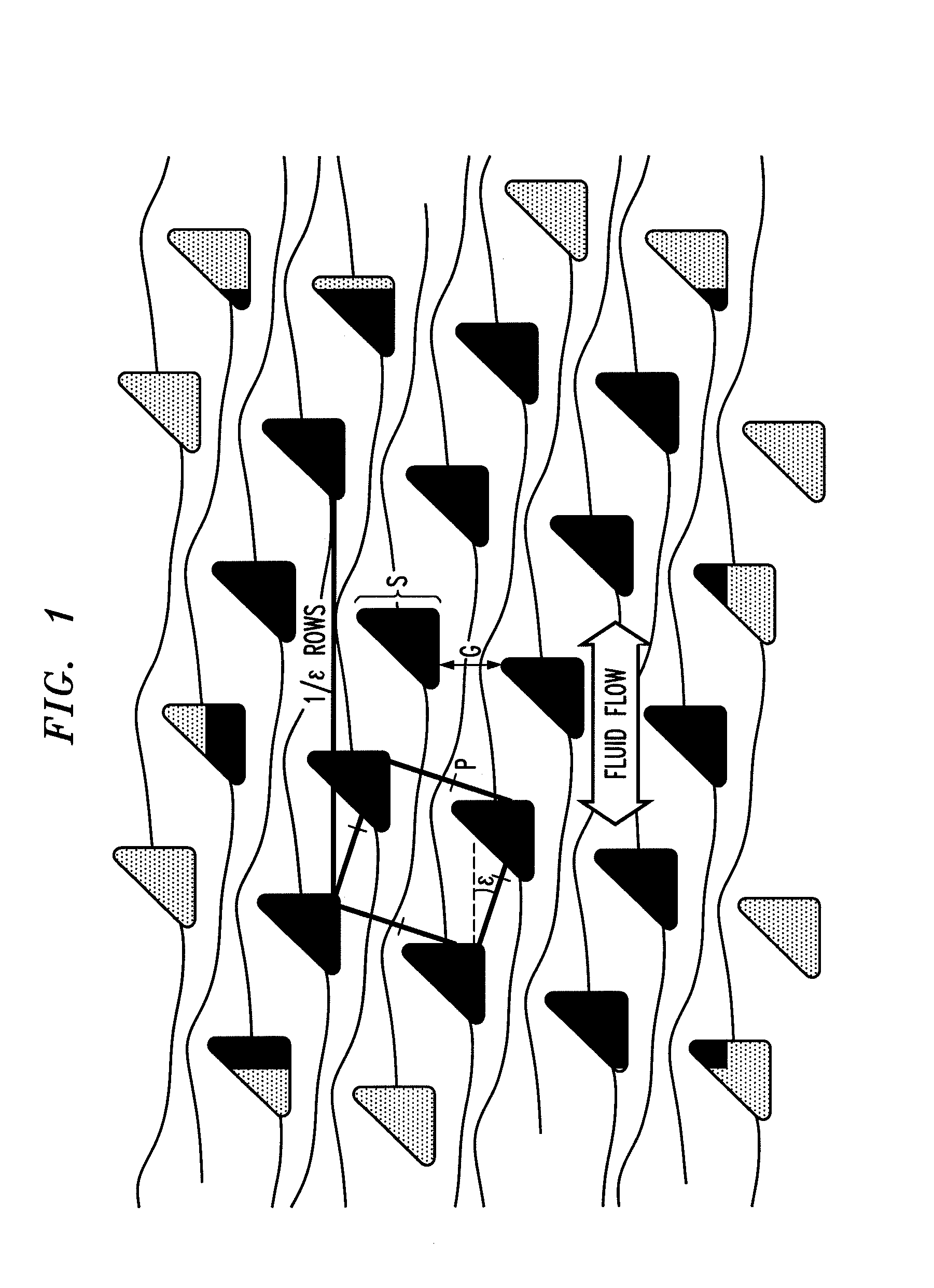
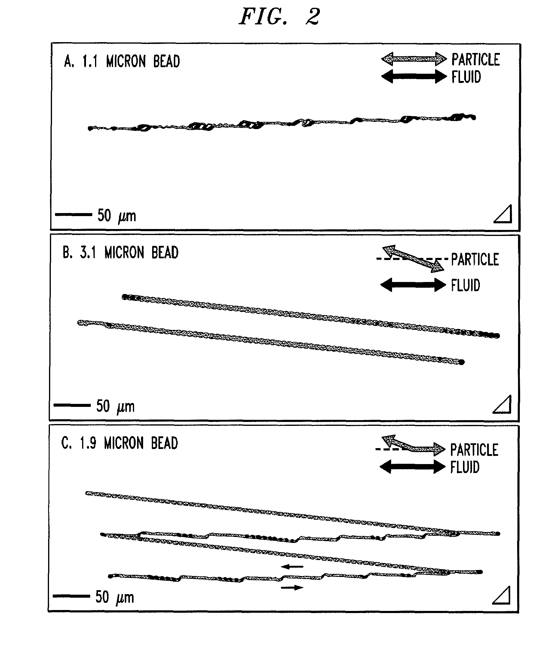
[0102]This example describes a microfluidic device in which the trajectory of particles within a certain size range varies with the direction the particles move through the device. This ratcheting effect is produced by employing triangular rather than the conventional circular posts in a deterministic lateral displacement device where an array of posts selectively displaces particles as they move through the array. This effect is then used to demonstrate a fractionation technique where particles can be separated from a fluid plug without any net motion of the original fluid plug. The underlying mechanism of this method is based on an asymmetric fluid velocity distribution through the gap between posts.

[0103]Microfluidic devices, such as those used in “lab on a chip” applications, typically operate at low Reynolds number (“low” Reynolds number refers to Reynolds number not greater than 1, and preferably smaller, such as 0.1, 10−3, or smaller). In t...

example 2

Bump Array Employing Triangular Posts

[0112]This example describes microfluidic arrays which sort particles based on size according to the deterministic lateral displacement method, by using triangular posts instead of the usual round posts. When triangular posts are used rather than round posts, and the triangular posts are properly oriented (i.e., such that the surfaces defining the gap are asymmetric), the critical size is decreased for a given gap size between the posts. This is because the different post geometry on either side of the gap causes an asymmetric flow profile through the gap, with flux shifting towards the vertex of the triangle. This shift in fluid flux reduces the width of the stream that determines the critical particle size. In this example, both experiment and modeling are used to show that changing the post shape from circular to triangular results in several practical advantages over similar arrays with circular posts including increased dynamic range and thr...


PUM


Abstract

The disclosure relates to obstacle array devices (also known as bump array devices) for separating populations of particles by size. Improvements over previous obstacle array devices are realized by causing the fluid velocity profile across gaps between obstacles to be asymmetrical with respect to the plane that bisects the gap and is parallel to the direction of bulk fluid flow. Such asymmetry can be achieved by selecting the shape(s) of the obstacles bounding the gap such that the portions of the obstacles upstream from, downstream from, or bridging the narrowest portion of the gap are asymmetrical with respect to that plane. Improvements are also realized by using obstacles that have sharp edges bounding the gaps. Other improvements are realized by selecting obstacle shapes such that the critical particle dimensions defined by the gaps in two different fluid flow directions differ.

Description

CROSS-REFERENCES TO RELATED APPLICATIONS[0001]This application is entitled to priority pursuant to 35 U.S.C. §119(e) to U.S. provisional patent application 61 / 135,854, which was filed on 24 Jul. 2008.STATEMENT REGARDING FEDERALLY SPONSORED RESEARCH OR DEVELOPMENT[0002]This work was supported in part by a grant from DARPA (Grant No. W911NF-07-1-0082), U.S. Air Force Office of Scientific Research (Grant No. FA9550-05-01-03), National Science Foundation Cornell Nanobiology Technology Center (Grant No. BSC-ECS9876771) and an STTR contract (National Institutes of Health contract no. 5R41CA128782-02) and the U.S. Government may have certain rights in this invention.BACKGROUND OF THE DISCLOSURE[0003]The disclosure relates generally to the field of separation of particles such as spheres, cells, viruses, and molecules. In particular, the disclosure relates to separation of particles based on their flow behavior in a fluid-filled field of obstacles in which advective transport of particles b...

Claims


Application Information

Patent Timeline
IPC IPC(8): B03B5/00
CPCB01L3/502753G01N27/44791G01N30/0005B03B5/00G01N30/6095G01N2030/528G01N30/6069
Inventor STURM, JAMES C.AUSTIN, ROBERTLOUTHERBACK, KEVINMORTON, KEITHPUCHALLA, JASON
Owner THE TRUSTEES FOR PRINCETON UNIV
Why Eureka
Try Eureka