
Method for ascertaining the speed of a starter

a technology of starter speed and speed, applied in the direction of engine starter, instrument, force/torque/work measurement apparatus, etc., can solve the problems of relative complexity and high cost, and achieve the effect of simple and cost-effective method for determining the speed of the starter

Inactive Publication Date: 2010-03-18
ROBERT BOSCH GMBH
View PDF12 Cites 15 Cited by
  • Summary
  • Abstract
  • Description
  • Claims
  • Application Information

AI Technical Summary

Benefits of technology

[0005]It is therefore an objective of the present invention to create a simple and cost-effective method for determining the speed of a starter.
[0007]An essential aspect of the present invention is to calculate the starter speed from electrical variables. This has the advantage in particular that the speed may be determined without a special speed sensor and in a particularly simple and cost-effective manner.

Problems solved by technology

This is relatively complex and expensive, however.

Method used


Image

  • Method for ascertaining the speed of a starter
  • Method for ascertaining the speed of a starter
  • Method for ascertaining the speed of a starter

Examples


Embodiment Construction

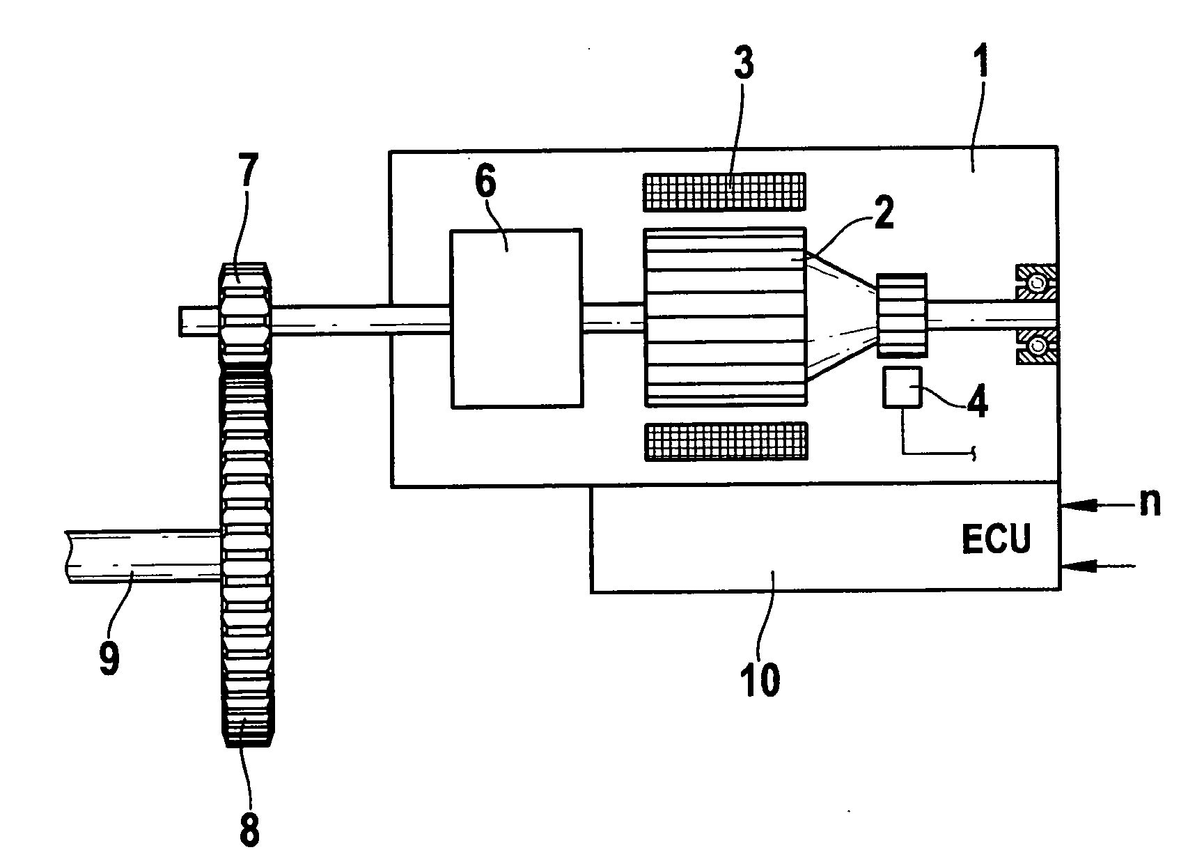
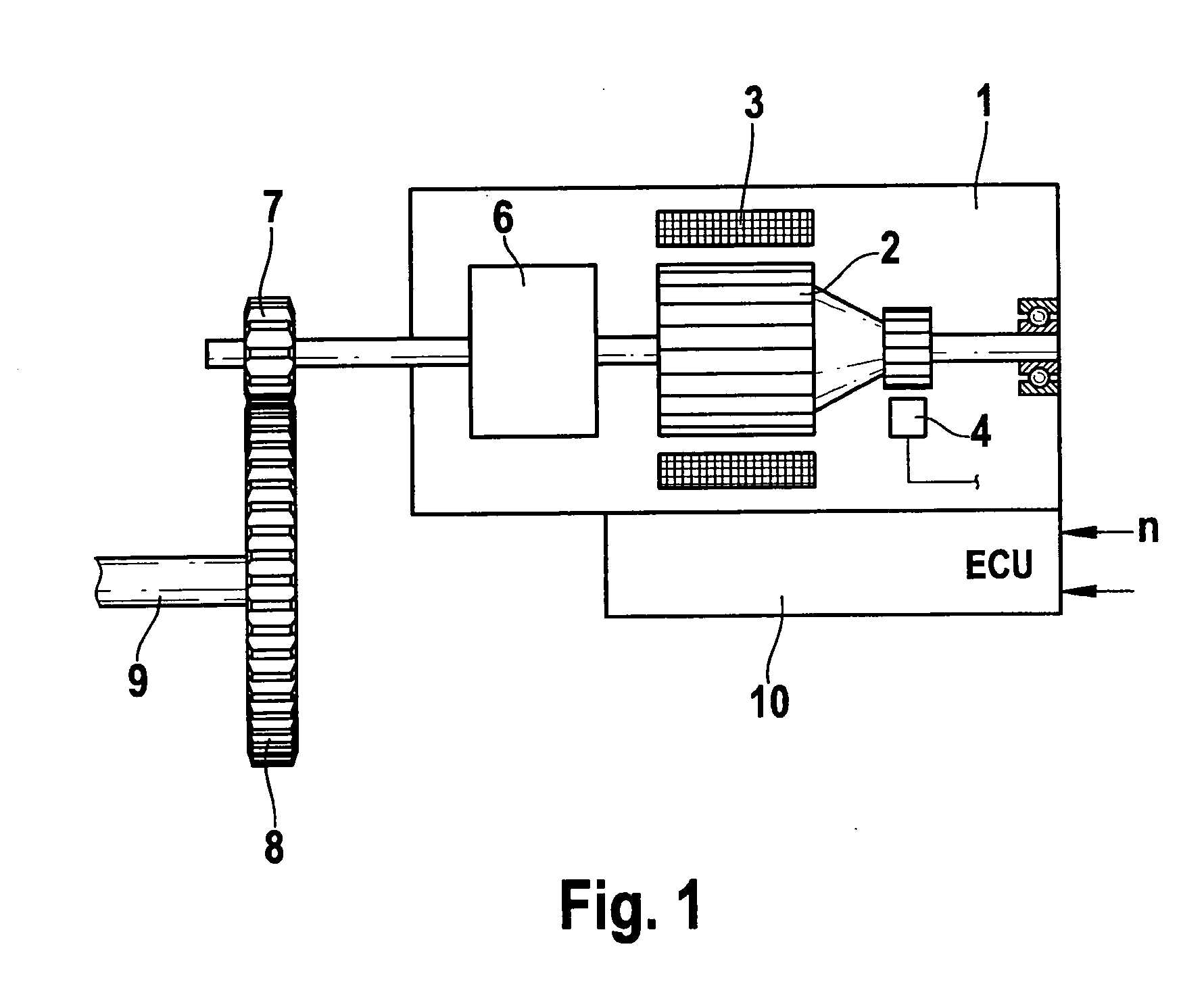
[0029]FIG. 1 shows a highly simplified schematic representation of a starter 1 for internal combustion engines as is used in particular in motor vehicles. Starter 1 includes essentially a direct current motor 2, 3, made up of an armature 2 having armature windings and a stator having several permanent magnets 3. The armature windings contained in armature 2 are supplied with electrical power via brushes 4. A pinion 7 is attached to motor shaft 5, which in a starting process engages into a ring gear 8 of crankshaft 9. An engaging mechanism 6 is provided for engaging and disengaging pinion 7, which usually includes an engaging lever and an engaging relay by which the main current path of starter 1 is switched.

[0030]Starter 1 includes its own starter control unit 10, which is used, among other things, to calculate the speed n of starter 1 and to control starter 1 accordingly. Starter 1 is in this case designed for use in vehicles that have a start-stop operation. In a start-stop operat...


PUM


Abstract

A method for determining the speed of a starter for starting internal combustion engines. The starter speed may be ascertained in a particularly simple and cost-effective manner in that it is calculated from different electrical variables and is calibrated by comparison to the internal combustion engine speed.

Description

FIELD OF THE INVENTION[0001]The present invention relates to a method for determining the speed of a starter for starting internal combustion engines.BACKGROUND INFORMATION[0002]Internal combustion engines of today's motor vehicles are generally started by a so-called pinion starter. The latter comprises essentially a direct current motor having a motor-driven pinion, which is engaged into a ring gear of the crankshaft and cranks the internal combustion engine when a start is requested. If the engine control unit initiates a start command, this start command causes a so-called engagement relay pulls up and engages the pinion into the ring gear of the crankshaft. If the engagement relay is pulled up, a main current path is automatically closed, which supplies the starter with electrical power. This starts the actual cranking process.[0003]In vehicles that are designed for start-stop operation, the pinion is in some cases engaged into the ring gear already before the internal combusti...

Claims


Application Information

Patent Timeline
Patent Type & Authority Applications(United States)
IPC IPC(8): G01M15/04
CPCF02N11/0844F02N11/0855F02N2200/041Y02T10/48F02N2200/044F02N2200/045H02P7/245F02N2200/043Y02T10/40H02P7/24F02N11/08G01B3/46
Inventor GE, JIEHEYERS, KLAUSTSAKIRIS, APOSTOLOS
Owner ROBERT BOSCH GMBH
Learn More