Planar gradient-index artificial dielectric lens and method for manufacture

a dielectric lens and gradient index technology, applied in the direction of electrical appliances, anti-statics, etc., can solve the problems of limited index variation range, difficult manufacturing, bulky dielectric lenses, etc., and achieve low loss gradient index, low distortion loss, and low distortion loss.

Inactive Publication Date: 2010-03-18
TOYOTA JIDOSHA KK
View PDF5 Cites 54 Cited by
  • Summary
  • Abstract
  • Description
  • Claims
  • Application Information

AI Technical Summary

Benefits of technology

[0007]By varying the dimension of conducting patches in a gradient direction, a gradient index lens may be readily obtained. Examples of the present invention include a planar artificial dielectric material comprising metal patches of varying dimension, thus having a refractive index that is a function of position. The variation of refractive index with spatial parameter may be designed according to a desired arbitrary formula. Lenses may be fabricated using conventional printed circuit board techniques, for example through the etching of metal patches on a metal coated dielectric substrate.
[0008]The use of geometrically simple metal patches, for example squares, avoids the presence of the relatively small features of the conducting metal patterns used in conventional metamaterials. Hence, an artificial dielectric lens can be fabricated using conventional multilayer printed wiring board technique. The propagation loss of the lens can be much lower than through a conventional metamaterial lens, because the artificial dielectric lens operates much further (in terms of frequency) from resonance than a metamaterial lens.
[0009]A great variation of index can be obtained by varying the parameters of the metal patches. For example, using square metal patches, an index variation ratio of 3 to 1 was obtained, comparing the highest index with lowest index within the same material. Hence, improved low loss gradient index lenses can be manufacturing using a simple and inexpensive technique.

Problems solved by technology

However, conventional dielectric lenses may be bulky, difficult to manufacture, and may provide a limited range of index variations.
However, conventional metamaterials require high resolution lithography which may limit the wavelength applications.
Further, when used near resonance losses in conventional metamaterials may be significant, and index variations may be limited.

Method used


Image

  • Planar gradient-index artificial dielectric lens and method for manufacture
  • Planar gradient-index artificial dielectric lens and method for manufacture
  • Planar gradient-index artificial dielectric lens and method for manufacture

Examples


Embodiment Construction

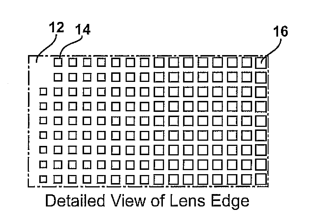
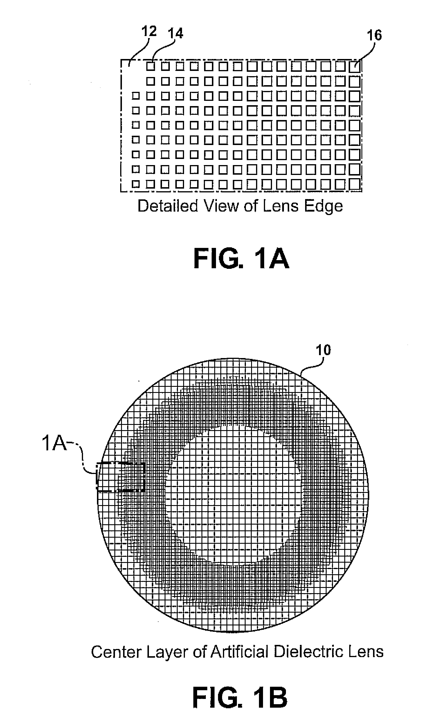
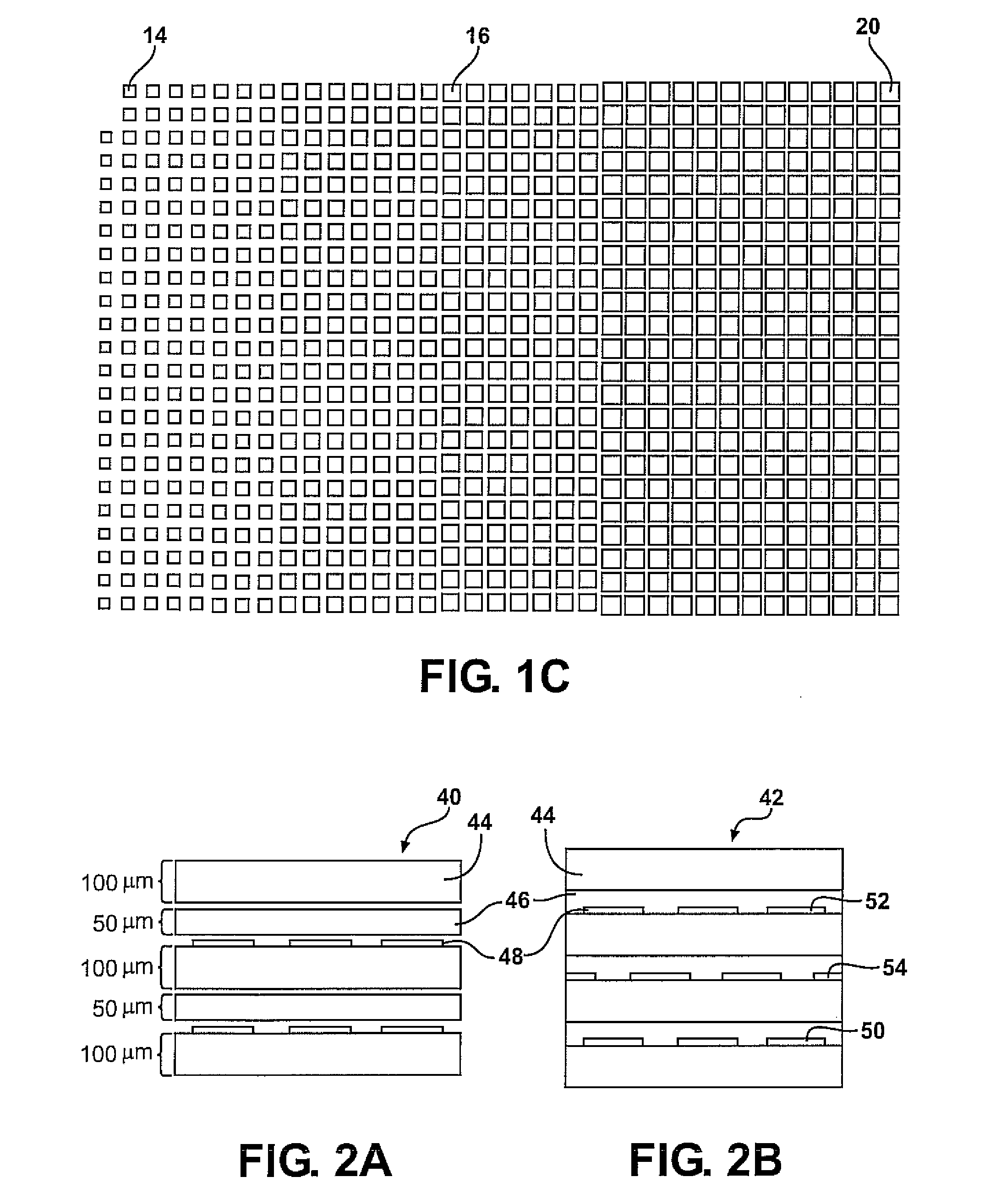
[0040]Examples of the present invention include artificial dielectric (AD) lenses, in particular gradient index lenses using artificial dielectric materials. A GRIN-AD lens may comprise an arrangement of square metal patches on a dielectric layer The edge lens of the square metal patches may vary as a function of a spatial position for example along a gradient direction. In some examples, the square lens and corresponding refractive index is a maximum in a center of the lens, and decreases as a function of radial distance from the lens center. Hence refractive elements can be obtained without the necessity of a curved surface, as is conventionally required with a normal dielectric lens.

[0041]Some examples of the present invention include multiple layer structures, for example formed from a plurality of printed circuit boards. The circuit boards may be spaced apart and bonded together, and copper layers on either single layer or double layer circuit boards may be etched to obtain the...


PUM


Abstract

A gradient index lens for electromagnetic radiation includes a dielectric substrate, a plurality of conducting patches supported by the dielectric substrate, the conducting patches preferably being generally square shaped and having an edge length, the edge length of the conducting patches varying with position on the dielectric substrate so as to provide a gradient index for the electromagnetic radiation. Examples include gradient index lenses for millimeter wave radiation, and use with antenna systems.

Description

FIELD OF THE INVENTION[0001]Examples of the invention relate to artificial dielectric materials, and applications thereof such as dielectric lenses for millimeter wave automotive radar.BACKGROUND OF THE INVENTION[0002]Radar systems, such as millimeter wave automotive radar, may benefit from the use of lenses or other beam modifying devices. However, conventional dielectric lenses may be bulky, difficult to manufacture, and may provide a limited range of index variations.[0003]Metamaterials have been used at radar wavelengths. However, conventional metamaterials require high resolution lithography which may limit the wavelength applications. Further, when used near resonance losses in conventional metamaterials may be significant, and index variations may be limited.[0004]Hence, improved lenses for use at millimeter waves and other wavelength ranges would be extremely useful.SUMMARY OF THE INVENTION[0005]Examples of the present invention include artificial dielectric lenses, in parti...

Claims


Application Information

Patent Timeline
Patent Type & Authority Applications(United States)
IPC IPC(8): H01Q15/08
CPCH01Q19/062H01Q15/08
Inventor NGYUEN, VINH N.YONAK, SERDAR H.
Owner TOYOTA JIDOSHA KK
Why Eureka
Try Eureka