
Continuous heat treatment furnace

a heat treatment furnace and continuous technology, applied in the direction of furnaces, heat treatment equipment, lighting and heating equipment, etc., to achieve the effect of preventing poor pickling property, facilitating omission of preliminary pickling, and facilitating descaling by post pickling

Inactive Publication Date: 2010-03-18
DAIDO STEEL CO LTD
View PDF9 Cites 10 Cited by
  • Summary
  • Abstract
  • Description
  • Claims
  • Application Information

AI Technical Summary

Benefits of technology

[0006]The present invention has been accomplished in view of the above problems, and an object thereof is to provide a continuous heat treatment furnace that enables easy atmosphere control in a heating chamber, omission of preliminary pickling in the case of treating a rolled material, and is also capable of obtaining a treated product having good post pickling property from each of both treatment objects, i.e. from each of a rolled material and a drawn material.
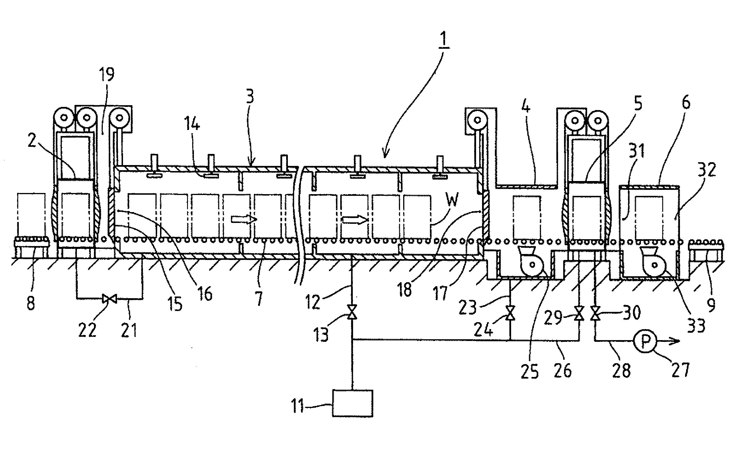
[0009]In case that the treatment object is a rolled material, after the heat treatment for the treatment object in the heating chamber is terminated, the treatment object transferred from the heating chamber is cooled in the first cooling chamber kept to the inert gas atmosphere such as N2. Accordingly, the rolling scale is decreased in temperature without being oxidized nor deoxidized, the phenomenon of transformation of wustite (FeO) in the rolling scale into magnetite (Fe3O4) which is rigid and has poor pickling property is prevented, thereby facilitating descaling by post pickling and enabling omission of preliminary pickling. Further, by performing rapid cooling at a cooling rate of 8° C. / min or more, more preferably at a cooling rate of 10° C. / min or more as the cooling, many cracks reaching to a surface of a matrix are formed on the rolling scale, whereby the descaling by post pickling becomes easier. The treatment object after the cooling is passed through the second cooling chamber via the vacuum purge chamber without any cooling treatment and discharged to the outside of the furnace.
[0010]On the other hand, in case that the treatment object is a drawn material, the treatment material after the heat treatment is transferred to the second cooling chamber via the first cooling chamber and the vacuum purge chamber without being cooled in the first cooling chamber and then subjected to cooling in the second cooling chamber kept to the oxidizing gas atmosphere. Accordingly, the carbide clung onto the surface of the drawn material is oxidized and the post pickling thus becomes easy. As the cooling in this case, rapid cooling at a cooling rate of 8° C. / min or more may preferably be performed in order to prevent a wustite layer on a drawn material surface from being transformed into magnetite due to the cooling. The treatment object after the cooling is discharged from the second cooling chamber to the outside of the furnace.
[0011]As described above, according to the present invention, it is possible to provide a continuous heat treatment furnace that realizes easy atmosphere control in the heating chamber and enables to omit preliminary pickling in the case of treating a rolled material as well as to obtain a treated product having good post pickling property from each of both treatment objects, i.e. from each of a rolled material and a drawn material. Also, since it is unnecessary to provide a dedicated heat treatment furnace separately for each of the rolled material and the drawn material, it is possible to reduce an equipment cost and installation space.

Problems solved by technology

However, in case that the treatment object is made from the above-described drawn material, it was found that a new problem that a lubricant adhered to a surface of the drawn material is carbonized due to the heating in the inert gas atmosphere and is not removed even in the post pickling step, resulting in disturbance for the following wire drawing step.

Method used


Image

  • Continuous heat treatment furnace
  • Continuous heat treatment furnace

Examples


Embodiment Construction

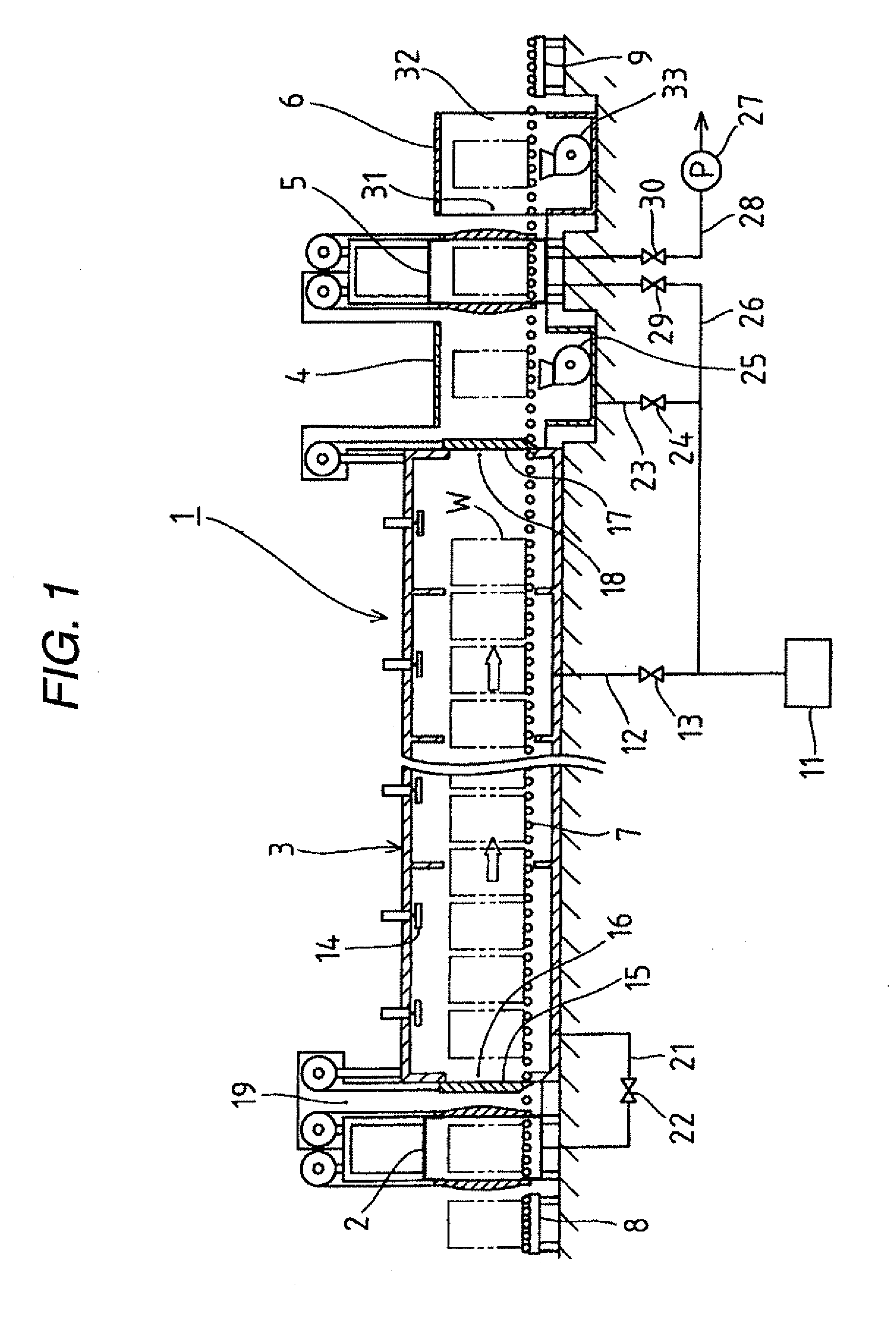
[0032]Hereinafter, one embodiment of the present invention will be described with reference to FIG. 1. FIG. 1 is a diagram showing whole of a continuous heat treatment furnace 1, in which a first cooling chamber 4, a vacuum purge chamber 5, and a second cooling chamber 6 are connected to one end of a heating chamber 3 provided with a front chamber 2 at the other end thereof. Denoted by 7 is a hearth roller provided along a whole length of the furnace for transferring a treatment object W; denoted by 8 is a charging table provided at the outside of an entrance of the front chamber 2; and denoted by 9 is a discharging table provided at the outside of an exit of the second cooling chamber 6.

[0033]The heating chamber 3 is used for heating the treatment object W in an inert gas atmosphere, and a N2 gas is used as the inert gas in this embodiment. The N2 gas is supplied to the heating chamber 3 via a piping 12 from a N2 gas generator 11 (gas cylinder), and denoted by 13 is an open / close v...


PUM

PropertyMeasurementUnit
diameteraaaaaaaaaa
concentrationsaaaaaaaaaa
temperatureaaaaaaaaaa

Abstract

The present invention provides a continuous heat treatment furnace including: a heating chamber heating a treatment object in an inert gas atmosphere; a front chamber provided at one end of the heating chamber; and a first cooling chamber cooling the treatment object in an inert gas atmosphere, a vacuum purge chamber, and a second cooling chamber cooling the treatment object in an oxidizing gas atmosphere, which are connected in this order to the other end of the heating chamber, in which the treatment object transferred from the front chamber to the heating chamber is subjected to the heating in the heating chamber, and then subjected to one cooling selected from the cooling in the inert gas atmosphere in the first cooling chamber and the cooling in the oxidizing gas atmosphere in the second cooling chamber depending on a type of the treatment object.

Description

FIELD OF THE INVENTION[0001]The present invention relates to a continuous heat treatment furnace for subjecting, to a heat treatment, a treatment object which is made from a steel material such as a wire material wound in the form of a coil and a rod stock material.BACKGROUND OF THE INVENTION[0002]A wire material or a rod stock material obtained by hot rolling (hereinafter referred to as rolled material) is subjected to an annealing treatment for improvement of processability in advance of a secondary processing such as wire drawing, and, in the case of performing further wire drawing for achieving a smaller diameter on a wire material that has been obtained by subjecting the rolled material to the wire drawing (hereinafter referred to as drawn material), another annealing treatment is further performed for improvement of processability.[0003]Since the rolled material among the above-described objects that will be treated by the annealing treatment has a rolling scale that is formed...

Claims


Application Information

Patent Timeline
Patent Type & Authority Applications(United States)
IPC IPC(8): F27D15/02
CPCC21D9/0056C21D9/0062F27D15/02F27B9/2407F27B9/042F27B9/02F27B9/12F27B9/20
Inventor ISHIMOTO, TAKASHIOCHIAI, TAKAYASHIMIZU, KENJIOGAWA, MASATO
Owner DAIDO STEEL CO LTD
Learn More