Method for operating an internal combustion engine

a technology of internal combustion engine and combustion chamber, which is applied in the direction of engine operation, non-fuel substance addition to fuel, exhaust gas recirculation, etc., can solve the problems of pressure drop or back pressure generation, loss of exhaust gas conducting system, etc., and achieve precise exhaust gas recirculation rate, improved control dynamics, and reduced fresh air volume

Inactive Publication Date: 2010-03-25
BENTELER AUTOMOBILTECHNIK GMBH
View PDF16 Cites 10 Cited by
  • Summary
  • Abstract
  • Description
  • Claims
  • Application Information

AI Technical Summary

Benefits of technology

[0013]According to another feature of the present invention, air flow sensors in the fresh-air line may be arranged to enable a determination of an exact mixing ratio of fresh air and exhaust gases and thus a precise exhaust gas recirculation rate. The air flow sensors may be arranged in such a way that a first air flow sensor is arranged upstream of the junction of the exhaust gas recirculation line to the fresh-air line to capture a fresh air volume flowing through an optionally arranged throttle flap. A second air flow sensor may be arranged in the exhaust gas recirculation line, advantageously near a junction of the exhaust gas recirculation line to the fresh-air line. In this configuration, the first air flow sensor detects directly the aspirated air volume, whereas the second air flow sensor detects the recirculated exhaust gas volume. It may, however, also be conceivable, to arrange the first air flow sensor downstream of the junction of the exhaust gas recirculation line to the fresh-air line so that the first air flow sensor is then able to ascertain the total volume flow (fresh air volume plus recirculated exhaust gases). As a result, the current EGR rate can be fully determined.
[0014]According to another advantageous feature of the present invention, the exhaust gas pressure may be detected by the pressure sensor, wherein advantageously the air flow sensors generate control signals for operating the control element. In order to be able to reach the necessary recirculation rate (recirculated exhaust gas volume) in accordance with the specifications of the motor management, the fresh air volume may be reduced for example by the arrangement of an additional throttle flap in the fresh-air line. In this way, the control dynamics can be enhanced. Operation of the throttle flap is however not necessarily required. As the recirculation rate is dependent on the crankshaft speed and the torque, adjustment of at least one control element can be controlled also by an appropriate functional combination of both signals so that the need for sensors can be eliminated.

Problems solved by technology

Exhaust gas conducting systems always experience losses as a result of pipe friction but also throttle losses as a result of pipe tapers, constrictions, or structures for flow dynamics.
Also filters, converters, mufflers, elbows, bends, and any obstacle in the flow path of the exhaust gas can cause a pressure drop or generation of back pressure.

Method used


Image

  • Method for operating an internal combustion engine
  • Method for operating an internal combustion engine
  • Method for operating an internal combustion engine

Examples


Embodiment Construction

[0029]Throughout all the figures, same or corresponding elements may generally be indicated by same reference numerals. These depicted embodiments are to be understood as illustrative of the invention and not as limiting in any way. It should also be understood that the figures are not necessarily to scale and that the embodiments are sometimes illustrated by graphic symbols, phantom lines, diagrammatic representations and fragmentary views. In certain instances, details which are not necessary for an understanding of the present invention or which render other details difficult to perceive may have been omitted.

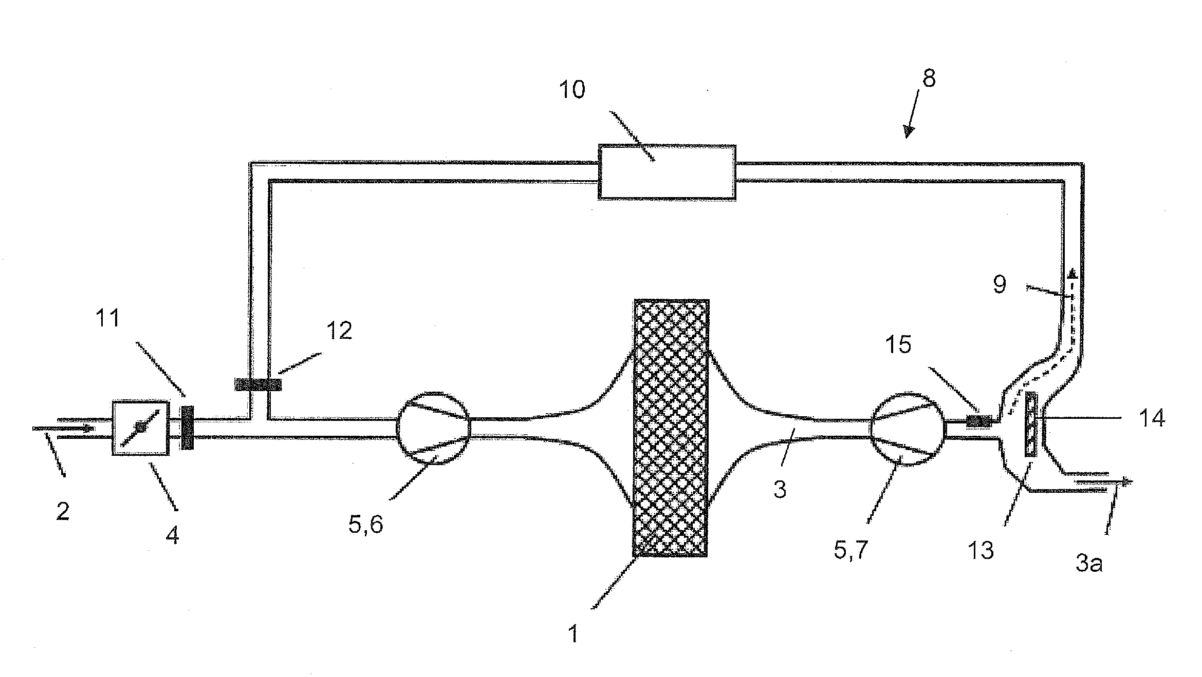
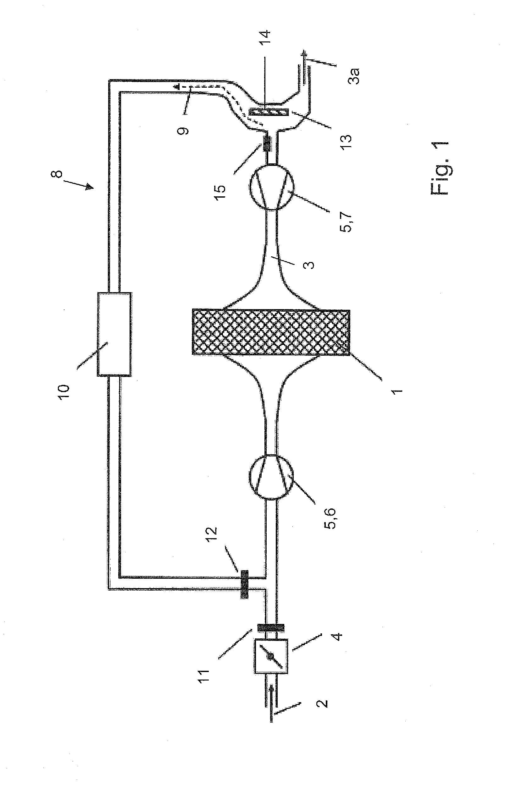
[0030]Turning now to the drawing, and in particular to FIG. 1, there is shown a basic schematic illustration of an internal combustion engine 1 having a fresh-air line 2 and an exhaust-gas line 3. A throttle valve 4 is disposed in the fresh-air line 2. The internal combustion engine 1 further includes a turbocharger 5 having a compressor 6 disposed in the fresh-air line 2 an...


PUM


Abstract

In a method of operating an internal combustion engine which has a fresh-air line, an exhaust-gas line, and an exhaust gas recirculation system, an exhaust gas flow is fed from the exhaust gas recirculation line of the exhaust gas recirculation system to the fresh-air line. The exhaust gas flow is hereby divided by a gas flow divider during flow from the exhaust gas recirculation line to the fresh-air line through actuation of a control element such that a first flow portion flows back to the exhaust gas recirculation line and a second flow portion flows to a continuing section of the exhaust-gas line. The exhaust gas recirculation system with the gas flow divider is operated substantially in the absence of a back pressure.

Description

CROSS-REFERENCES TO RELATED APPLICATIONS[0001]This application claims the priority of German Patent Application, Serial No. 10 2008 048 973.5, filed Sep. 25, 2008, pursuant to 35 U.S.C. 119(a)-(d), the content of which is incorporated herein by reference in its entirety as if fully set forth herein.BACKGROUND OF THE INVENTION[0002]The present invention relates to a method of operating an internal combustion engine.[0003]The following discussion of related art is provided to assist the reader in understanding the advantages of the invention, and is not to be construed as an admission that this related art is prior art to this invention.[0004]Examples of an internal combustion engine include an Otto engine or a Diesel engine in which a portion of exhaust gas is recirculated to a fresh-air line via an exhaust gas recirculation line to thereby reduce oxygen concentration and thus to cause a reduction in the nitrogen oxide emission. Internal combustion engines may be charged, e.g. with a...

Claims


Application Information

Patent Timeline
Patent Type & Authority Applications(United States)
IPC IPC(8): F02M25/07F01N1/00F02M25/06
CPCF02D41/0065F02D41/0077F02D41/1448F02D41/18F02D2041/0075Y02T10/47F02M25/0709F02M25/0713F02M25/0719F02M25/0727F02M25/0754F02D2250/34F02M26/06F02M26/10F02M26/16F02M26/23F02M26/47Y02T10/40
Inventor RABE, FRANKRICHTER, BJORNNIESSE, MAX
Owner BENTELER AUTOMOBILTECHNIK GMBH
Why Eureka
Try Eureka