
Chemical mechanical polishing aqueous dispersion and chemical mechanical polishing method

a chemical mechanical and polishing technology, applied in lapping machines, other chemical processes, manufacturing tools, etc., can solve the problems of difficult depositing of metal in via-holes, erosion, and inability to obtain flat polished surfaces

Active Publication Date: 2010-03-25
JSR CORPORATIOON +1
View PDF23 Cites 35 Cited by
  • Summary
  • Abstract
  • Description
  • Claims
  • Application Information

AI Technical Summary

Benefits of technology

The invention provides a chemical mechanical polishing aqueous dispersion that can effectively polish targets containing tungsten, including interconnect layers and insulating films with via-holes and tungsten films. The dispersion includes a cationic water-soluble polymer, an iron (III) compound, and colloidal silica particles. The content of the polymer and iron compound are specifically designed to achieve optimal polishing results. The dispersion has a pH of 1 to 3. The invention also provides a chemical mechanical polishing method using this dispersion, which can effectively polish tungsten and barrier metal films simultaneously with insulating films.

Problems solved by technology

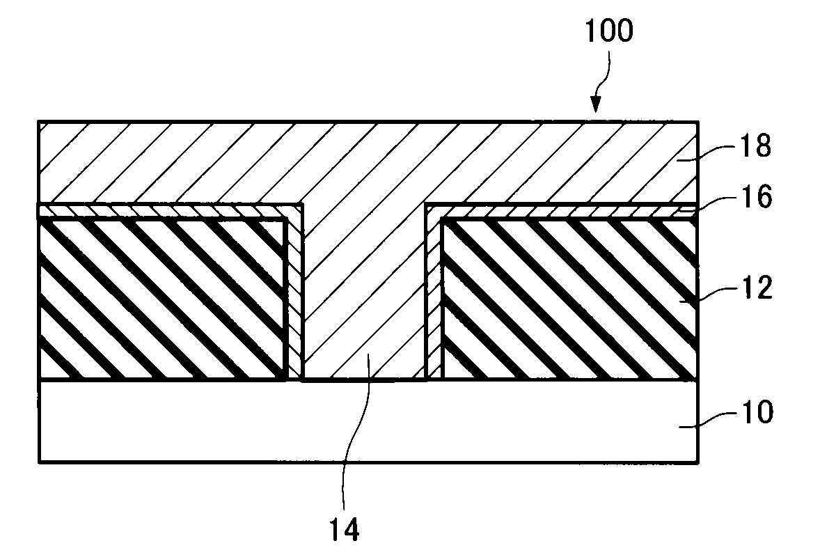
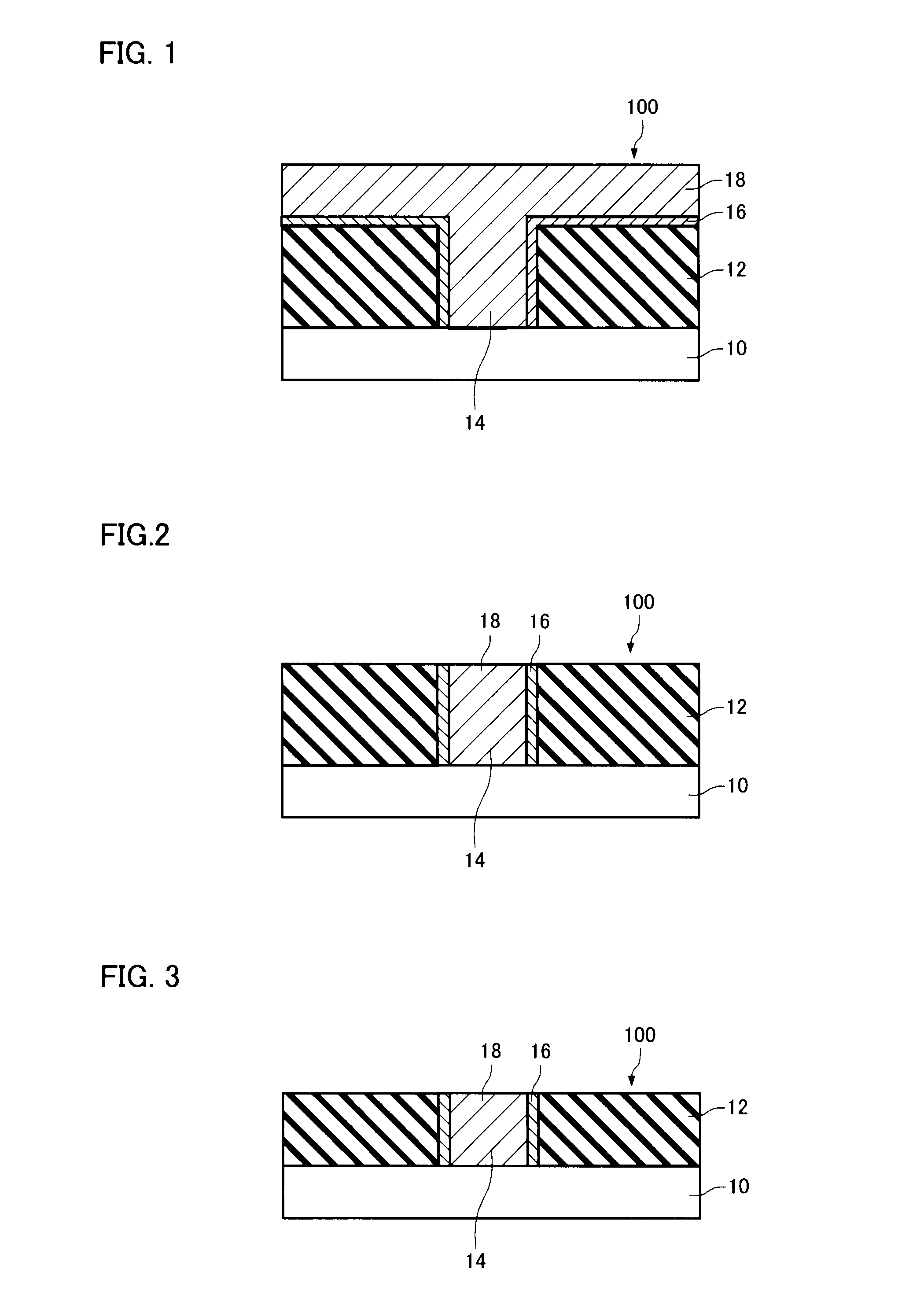
It is difficult to deposit a metal in a via-hole (i.e., fill the via-hole with a metal) in a minute interconnect area of a high-performance integrated circuit.
However, since the above pH range of the polishing composition is not practical when the polishing composition is used to polish a tungsten-containing material, a flat polished surface cannot be obtained when polishing tungsten using the polishing composition having a pH within the above range.
Along with a recent reduction in interconnect width, erosion (wear) that occurs in a minute interconnect area poses a problem with regard to flatness.
It is considered that erosion occurs due to dishing (depression) that occurs in a tungsten interconnect area and thinning (wear) that subsequently occurs in silicon oxide positioned between the tungsten interconnects.
However, since the highly selective polishing composition has a strong effect on a tungsten film, a deterioration in flatness (dishing) may occur in a wide interconnect area, or the surface of the tungsten film may be roughened, for example.
On the other hand, since the nonselective polishing composition does not achieve nonselectivity at a high polishing rate, the polishing rate must be decreased.

Method used


Image

  • Chemical mechanical polishing aqueous dispersion and chemical mechanical polishing method
  • Chemical mechanical polishing aqueous dispersion and chemical mechanical polishing method
  • Chemical mechanical polishing aqueous dispersion and chemical mechanical polishing method

Examples


Embodiment Construction

[0024]The invention may provide a chemical mechanical polishing aqueous dispersion and a chemical mechanical polishing method used to nonselectively polish a tungsten-deposited semiconductor wafer at high speed.

[0025]According to one embodiment of the invention, there is provided a chemical mechanical polishing aqueous dispersion that is used to polish a polishing target that includes an interconnect layer that contains tungsten, the chemical mechanical polishing aqueous dispersion comprising:

[0026](A) a cationic water-soluble polymer;

[0027](B) an iron (III) compound; and

[0028](C) colloidal silica particles,

[0029]the content (MA) (mass %) of the cationic water-soluble polymer (A) and the content (Mn) (mass %) of the iron (III) compound (B) satisfying the relationship “MA / MB=0.004 to 0.1”; and

[0030]the chemical mechanical polishing aqueous dispersion having a pH of 1 to 3.

[0031]In this chemical mechanical polishing aqueous dispersion, the cationic water-soluble polymer (A) may be pol...


PUM

PropertyMeasurementUnit
pHaaaaaaaaaa
particle diameteraaaaaaaaaa

Abstract

A chemical mechanical polishing aqueous dispersion is used to polish a polishing target that includes an interconnect layer that contains tungsten. The chemical mechanical polishing aqueous dispersion includes: (A) a cationic water-soluble polymer; (B) an iron (III) compound; and (C) colloidal silica particles. The content (MA) (mass %) of the cationic water-soluble polymer (A) and the content (MB) (mass %) of the iron (III) compound (B) satisfy the relationship “MA / MB=0.004 to 0.1”. The chemical mechanical polishing aqueous dispersion has a pH of 1 to 3.

Description

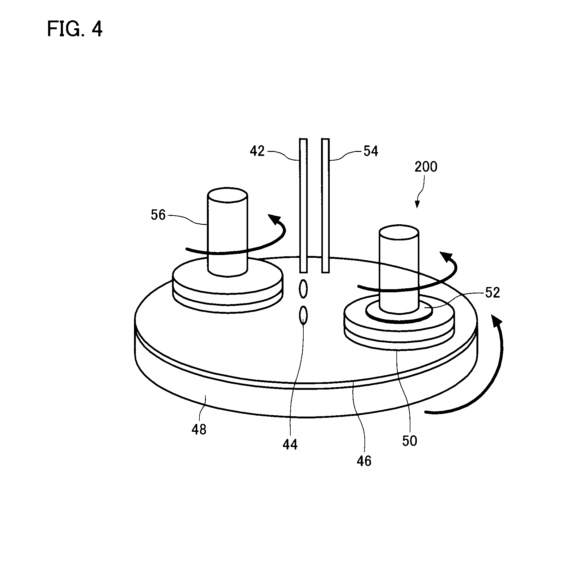
[0001]Japanese Patent Application No. 2008-240851, filed on Sep. 19, 2008, is hereby incorporated by reference in its entirety.BACKGROUND OF THE INVENTION[0002]The present invention relates to a chemical mechanical polishing aqueous dispersion and a chemical mechanical polishing method.[0003]In recent years, interconnects formed in semiconductor devices have been increasingly scaled down along with an increase in the degree of integration of semiconductor devices. In view of such a situation, a chemical mechanical polishing (hereinafter may be referred to as “CMP”) that planarizes various films (metal film and planarization sacrificial film) method that form a semiconductor device by utilizing a chemical effect and a mechanical effect has been used.[0004]Specifically, a conductor metal (e.g., aluminum, copper, or tungsten) is deposited by sputtering, plating, or the like in a minute groove (hereinafter referred to as “via-hole”) formed in an insulating film (e.g., silicon oxide) for...

Claims


Application Information

Patent Timeline
Patent Type & Authority Applications(United States)
IPC IPC(8): H01L21/304C09K13/00B24B37/00C09K3/14
CPCC09K3/1463H01L21/7684H01L21/3212C09K13/06
Inventor ABE, TAICHISHIDA, HIROTAKATAKEMURA, AKIHIROMENO, MITSURUHIRASAWA, SHINICHIIWADE, KENJINISHIOKA, TAKESHI
Owner JSR CORPORATIOON
Learn More