
Combustion system with precombustor

a combustion system and pre-combustion technology, applied in the field of combustion systems, can solve the problems of increasing the enthalpy loss of stacks, increasing the fan power requirement, and increasing the energy demand, so as to increase the residence time and increase the flame stability

Inactive Publication Date: 2010-04-01
AIR PROD & CHEM INC
View PDF15 Cites 43 Cited by
  • Summary
  • Abstract
  • Description
  • Claims
  • Application Information

AI Technical Summary

Benefits of technology

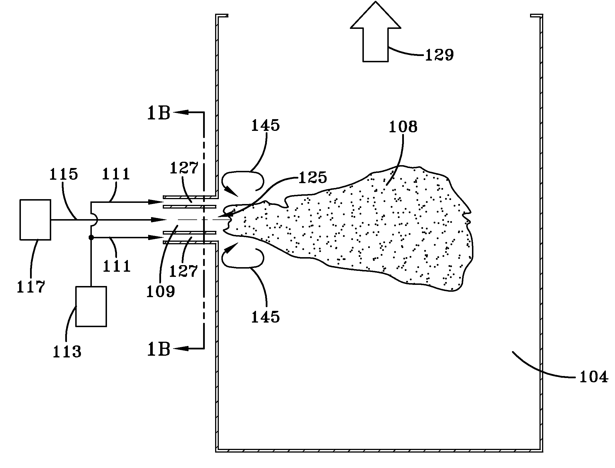
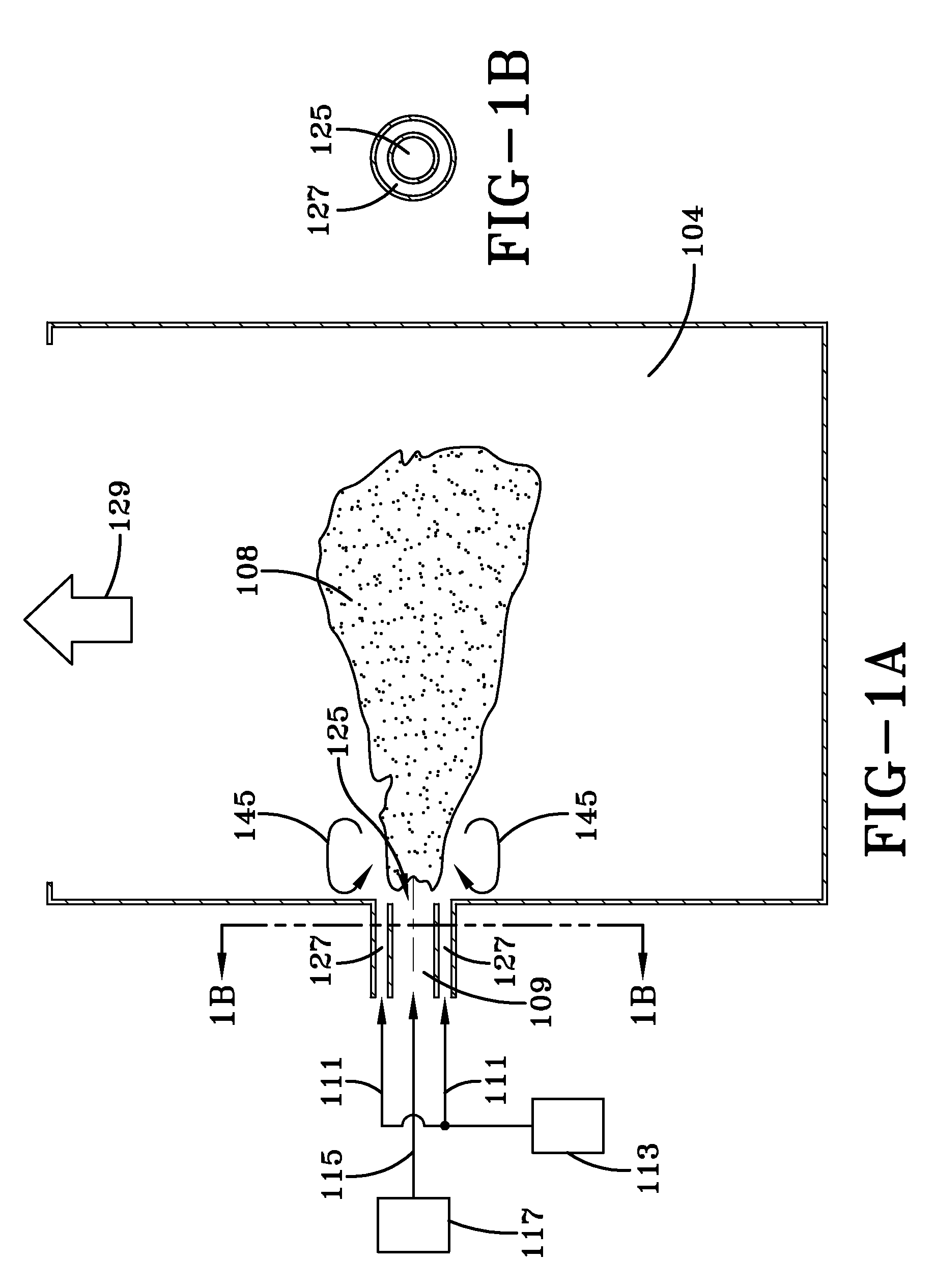
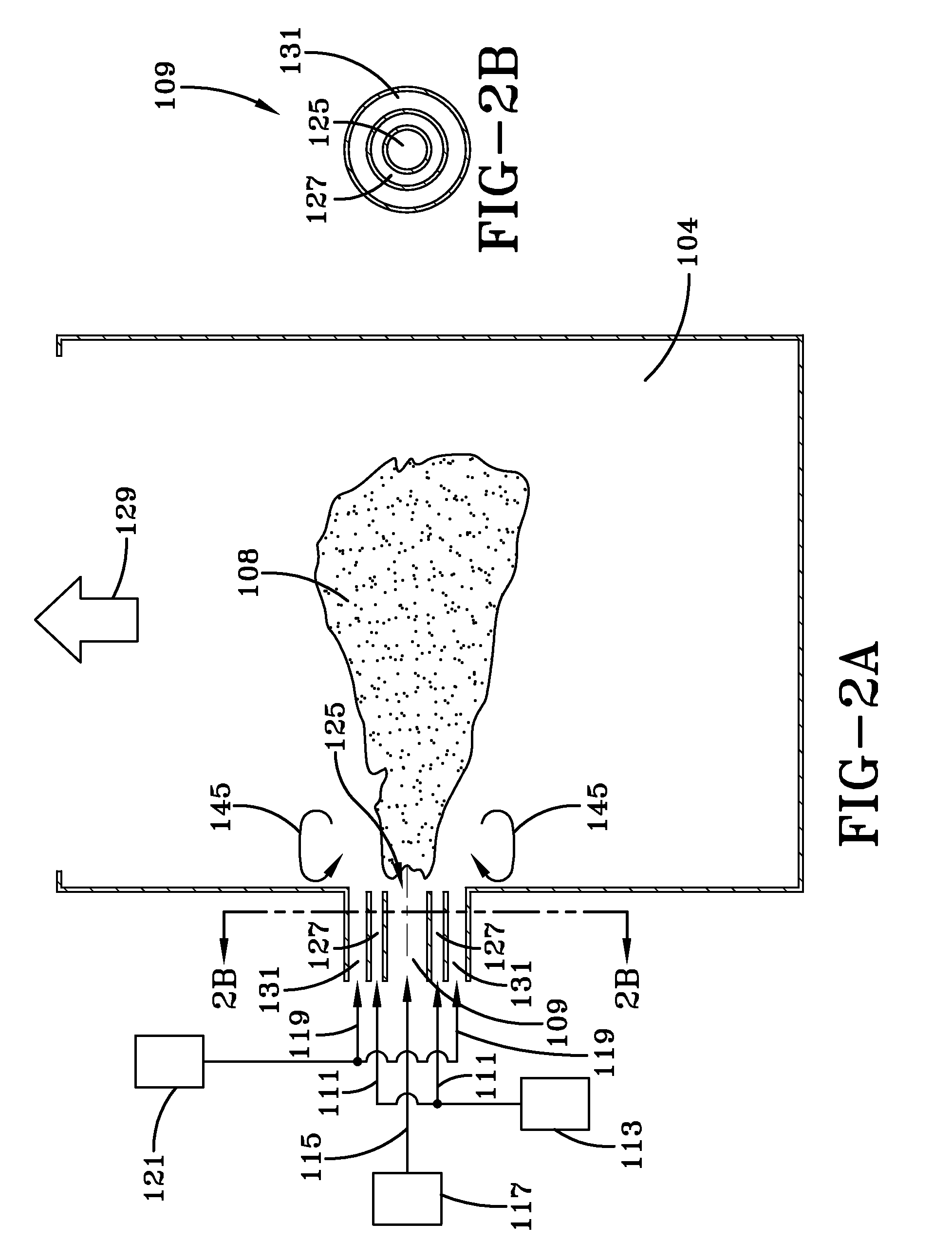
[0010]Still another further advantage of embodiments of the present disclosure is increased residence time and more complete combustion prior to and immediately after entry into the furnace.
[0011]Still another advantage of embodiments of the present disclosure is that recirculation zones serve as a buffer providing thermal protection for the walls of the precombustor.
[0012]Another advantage of the embodiments of the present disclosure is that the recirculation zones serve as a buffer providing protection between the corrosive furnace environment and the burner nozzle.
[0013]Another advantage of the embodiments of the present disclosure is increased flame stability.

Problems solved by technology

Energy demands are an ongoing problem in the United States and world-wide.
While operating with a higher stoichiometric ratio, air-coal combustion results in higher fan power requirements (typically a fraction of a percent of gross power generation of the steam turbine) and stack sensible enthalpy losses.

Method used


Image

  • Combustion system with precombustor
  • Combustion system with precombustor
  • Combustion system with precombustor

Examples


Embodiment Construction

[0047]As used herein, the term “solid fuel” refers to any solid fuel suitable for combustion purposes. For example, the disclosure may be used with many types of solid fuels, including but not limited to: anthracite, bituminous, sub-bituminous, and lignitic coals; tar; bitumen; petroleum coke; paper mill sludge solids and sewage sludge solids; wood; peat; grass; and combinations and mixtures of all of those fuels. As used herein, the term “oxygen” refers to an oxidizer with an O2 concentration greater than 30 mol %; preferably greater than 80 mol %. As used herein, the term oxy / coal combustion refers to coal combustion in oxygen, the term air / coal combustion refers to coal combustion in air, the term oxy / fuel combustion refers to solid fuel combustion in oxygen, and the term air / fuel combustion refers to solid fuel combustion in air. As used herein, the term “combustion fluid” refers to a fluid formed from and / or mixed with the products of combustion, which may be utilized for conve...


PUM


Abstract

A precombustor having a chamber having a first end and a second end, and an inlet configured to deliver a substantially parallel flow of solid fuel surrounded by oxygen at the first end. The first end further includes a recirculation step and the second end fluidly communicates with a furnace. The inlet and the recirculation step are arranged to form a recirculation zone of at least a portion of the solid fuel and the oxygen. A combustion system and method for operating a combustion system are also disclosed.

Description

CROSS-REFERENCE TO RELATED APPLICATIONS[0001]This application is related to application Ser. No. ______, entitled “OXY / FUEL COMBUSTION SYSTEM WITH LITTLE OR NO EXCESS OXYGEN”, Attorney Docket No. 07228 USA, filed contemporaneously with this application on Sep. 26, 2008, assigned to the assignee of the present disclosure and which is herein incorporated by reference in its entirety, application Ser. No. ______, entitled “COMBUSTION SYSTEM WITH STEAM OR WATER INJECTION”, Attorney Docket No. 07238 USA, filed contemporaneously with this application on Sep. 26, 2008, assigned to the assignee of the present disclosure and which is herein incorporated by reference in its entirety, application Ser. No. ______, entitled “OXY / FUEL COMBUSTION SYSTEM WITH MINIMIZED FLUE GAS RECIRCULATION”, Attorney Docket No. 07257 USA, filed contemporaneously with this application on Sep. 26, 2008, assigned to the assignee of the present disclosure and which is herein incorporated by reference in its entirety,...

Claims


Application Information

Patent Timeline
IPC IPC(8): F23B10/00F23B80/00F23J15/00F23L7/00
CPCF23C6/04Y02E20/344F23L7/007F23C9/003Y02E20/34
Inventor SLAVEJKOV, ALEKSANDAR GEORGIHE, XIAOYID'AGOSTINI, MARK DANIELHENDERSHOT, REED JACOB
Owner AIR PROD & CHEM INC
Learn More