Method and means for connecting and controlling a large number of contacts for electrical cell stimulation in living organisms

a technology of electrical cell stimulation and contact, applied in the field of cellular electrical stimulation, can solve the problems of reducing the success of dbs procedures, not optimal positioning, and many forms of parkinson's diseases

Active Publication Date: 2010-04-01
LEE CHONG IL +1
View PDF11 Cites 99 Cited by
  • Summary
  • Abstract
  • Description
  • Claims
  • Application Information

AI Technical Summary

Benefits of technology

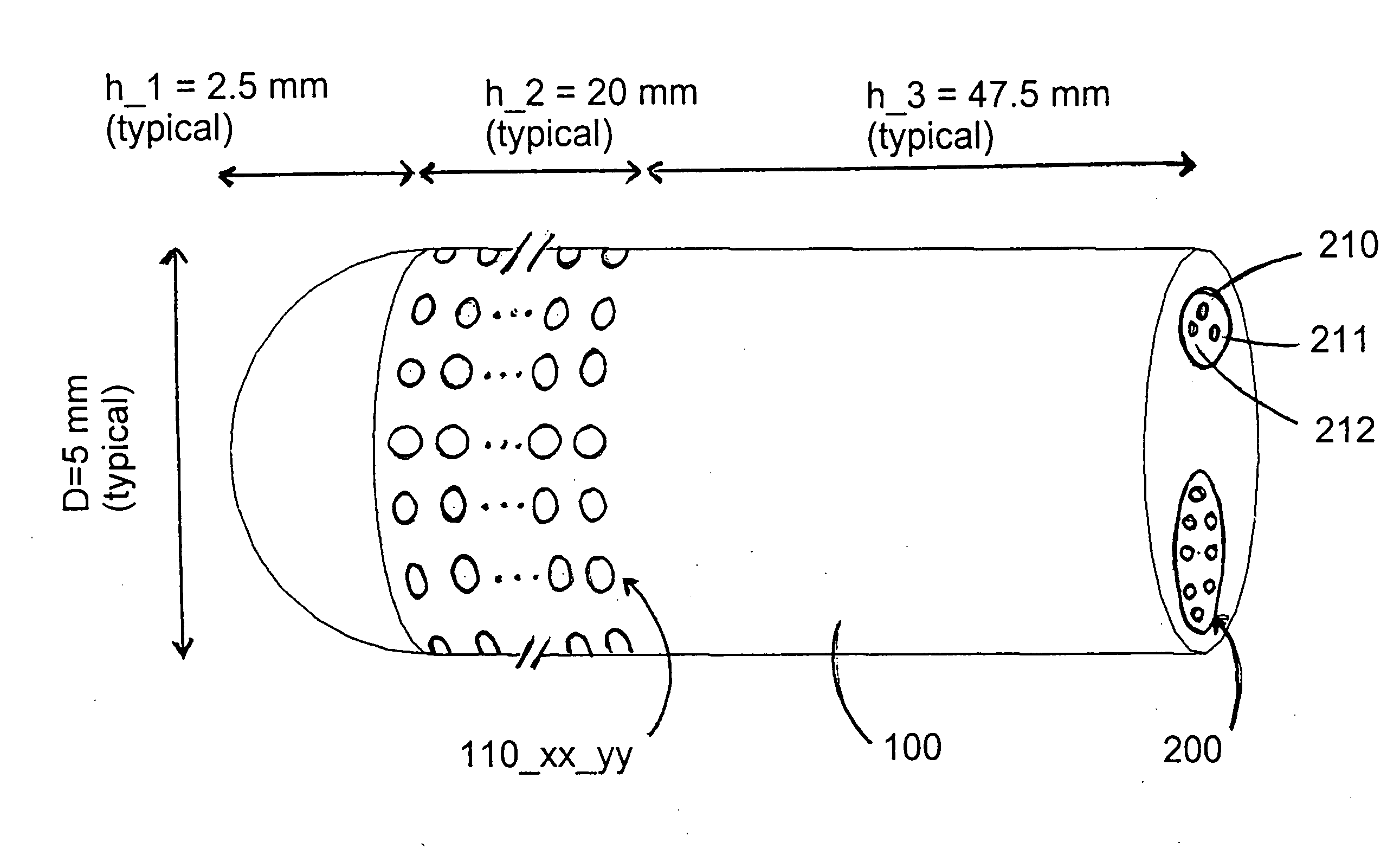
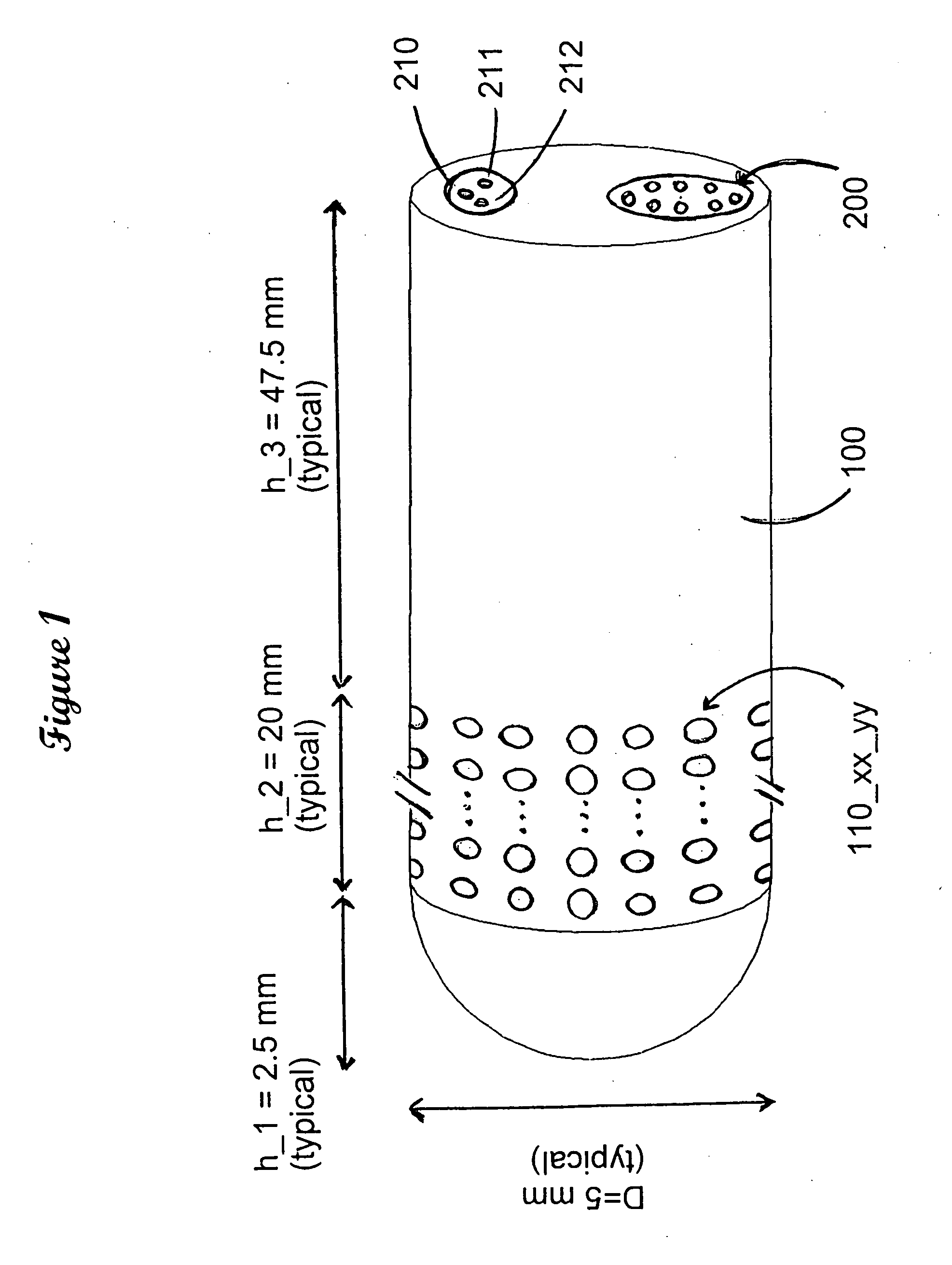
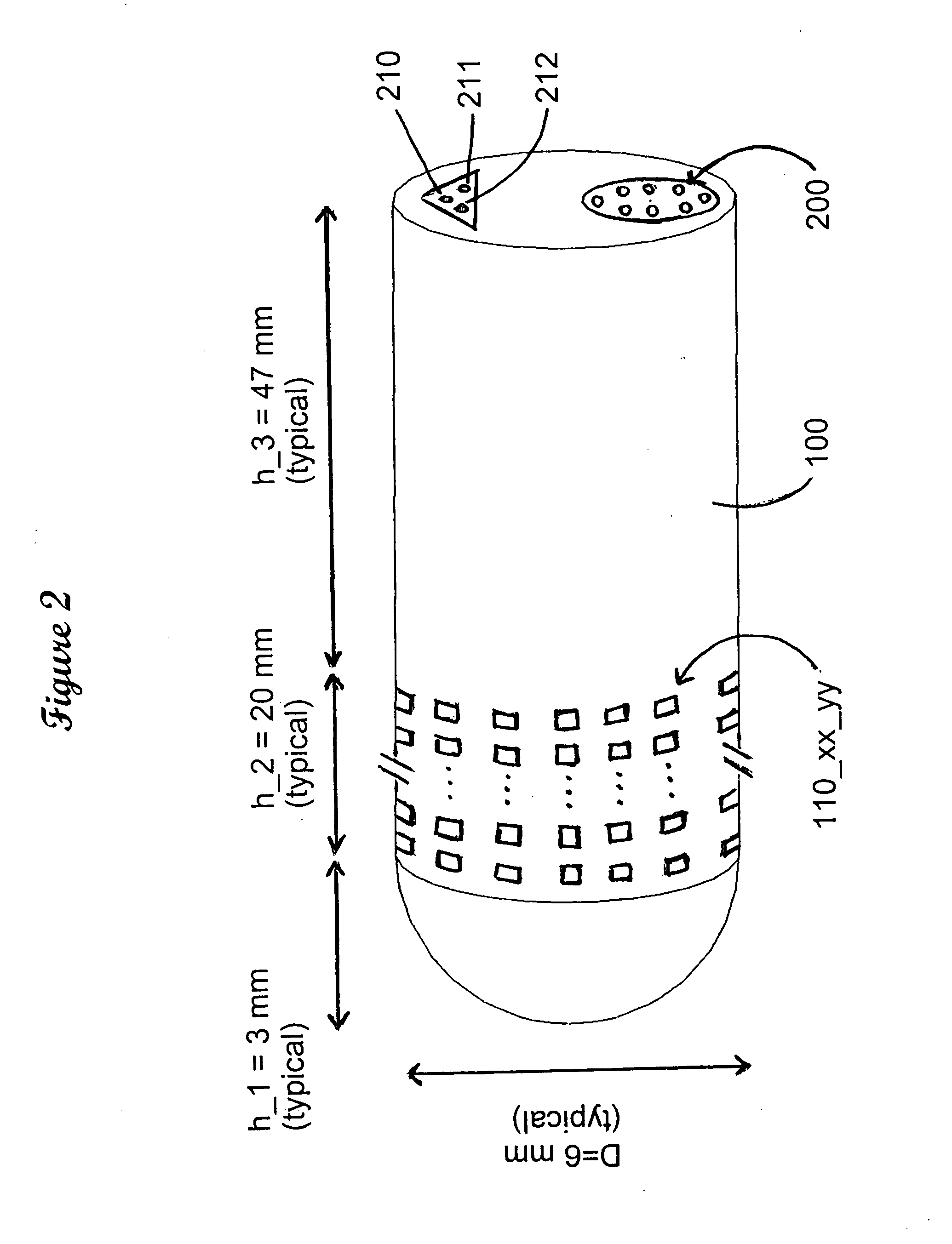
[0131]For said selection of pads and voltage levels, the medical practitioner will either use a system recommended by the picafina manufacturer, or will use a system developed by him / herself to test variations of pads and voltages that are best for the patient. For example, the discovery session may start selecting all the 12 most distal pads, that is, pads 120_01_01 through 120— 01_12 at a low voltage, say 0.5 V. The medical practitioner will then send the information from his / her DPU, via the wireless system, to the implanted unit and then press another software bottom that instructs the implanted unit to start sending the pulses to the picafina. The patient will report the effect, if any. Depending on the effect on the patient, as reported by him / her, and as observed by the medical practitioner, this latter may increase the voltage to 1.0 V and try again, in 0.5 V steps (or any other step) until some effect is reported by the patient or until the maximum allowed is reached, usually near 5 V. This series may be stopped short if undesirable side effects were reported by the patient. At this point, if undesirable side effects were either reported by the patient (say, depression) or observed by the medical practitioner (say, facial pulling), the medical practitioner may try turning on a subset of the pads, say, pads 120_01_01 through 120_01_06. This is the equivalent at the picafina level to selecting a particular angular section of the ring, which physically directs the current onto a particular direction only around the picafina. The medical practitioner will try other combinations too, as indicated by geometry and his / her experience, observing if the undesirable side effects appear or disappear. At this point the medical practitioner will be investigating the current injection towards one side of the picafina, as opposed to all around it. If the undesirable side effect fails to appear when turning on a subset of the pads, then this may be an indication that this set points toward the bulk of the area-of-interest, because it is known that the picafina is often positioned at some edge of the area-of-interest. Next the medical practitioner may use his / her Doctor's Programming Unit (DPU) to turn off all the most distal pads and turn on instead the second next ring of pads towards the proximal end of the picafina, pads numbered 120_02_01 through 120_02_12. He / she will again run the series of allowed voltage levels, increasing the voltage by steps of 0.5 volts, in consultation with the patient, noting all the results, also stopping if undesirable side effects were observed. If undesirable side effects were observed on the most distal set of pads but not when a subset only of pads were turned on, the medical practitioner may then try the same “good” set on this second ring of pads 120_02_xx. This may confirm the previous observation that the picafina is located near the edge of the region-of-interest, with a particular range of pads towards the region-of-interest.
[0132]The medical practitioner may then go to ring number 3 (120_03_xx, pads 120_03_01 through 120_03_12), then ring number 4, etc, until the most proximal ring, number 16. Upon completion of this initial series, the medical practitioner may decide to make a more detailed investigation on the effect of some particular pads, depending on the total of reported and observed results, and so on.

Problems solved by technology

Yet, many forms of Parkinson's diseases and other movement disorders too, are either unresponsive or only partially ameliorated by DBS (Okun (2006)).
It is unknown the causes of the differences, but one of the speculations is not optimal positioning of the stimulating electrode, which would, as expected, fail to have optimal effect in this case due to failure to stimulate the chosen area.
Additionally, the success of DBS procedures can diminish over time.
This latter decrease in efficacy of DBS is thought by some neurosurgeons to arise from motion of the implant inside the brain due to occasional sudden head movements, particularly due to a falling but also other causes.
Known side effects from brain stimulators caused it to be recognized the need for smaller electrode area for neural stimulation, but since nobody has been able to precisely position the stimulator in the brain, the only option has been to stimulate an area that is likely to be larger than necessary.
This has been a widely known problem in the art of brain stimulators: unwanted side effects, as mood changes, uncontrolled motion of other muscles not intended to be affected, etc.
Yet their device assumes that the implant is indeed positioned at the desired target location, which the neurosurgeons know to be a very difficult task.
Indeed, the difficulty of this task is indicated by the acceptance by the neurosurgeon community of the side effects, which arises from incorrect positioning of the stimulating device, which then applies electrical current also into undesired areas, thereby causing the known side effects.
Present MCS techniques, however, fail to address or adequately consider a variety of factors that may enhance or optimize the extent to which a patient experiences short term and / or long term relief from PD symptoms.” Which is likely to be a consequence that their invention is unable to precisely adjust the point of application of electrical stimulation, which is exactly the solution proposed by our invention.
Yet Pianca's invention suffers from the disadvantage of increased trauma to the patient due to multiple insertions and withdraws of invasive instruments in the brain.
Pless device again fails to teach any means to precisely measure and to precisely insert the electrical corrective pulse.
Potential movement of the device, as well as other characteristics, are also disclosed in another US patent by Carl Wahlstrand (Wahlstrand (2008)), but again these inventors fail to solve the problem of the number of electrodes and the possible number of wires to use.
Their device lacks the flexibility of choice of electrical initiation point that our device has.
Therefore current art does not solve the problem of directionality, apparently because nobody has been able to have a large number of point-like smaller electrical contacts all over the picafina, and capable of being independently turned on or off as needed.
This lack of directionality is not good because the picafina is seldom positioned at the dead center of the target location—the surgeon cannot see inside the brain as he / she inserts the picafina, and the regions look the same anyway, so even if the surgeon were able to see the region near the picafina when it is inserted, it would make little difference for its positioning.
It follows that the electrode positioning is less accurate than desirable.
Exact position of the picafina is also difficult because of the target regions are usually small, of the order of a few mm only.
Neither is satisfactory, because when the electrical current does not perfuse the target area there is under-treatment, while when the current invades nearby areas there may occur side effects due to stimulations of areas that are not intended to be stimulated.
If the picafina is of a newer type, already in the market, with square or circular pads, the current can be injected in one or more directions, as needed, but with insufficient positional control, also not ideal for the patient.
It appears that Medtronic is trying to solve the directional problem but have been unable to add more pads, most likely due to lack of space for individual wires inside the picafina.
It stands to reason that in all cases when the inserting rod is close to the edge of the target region, shooting the current in all directions is not desirable, as the current will enter in areas that would be better left alone, as they are functioning normally.
It seems that the last possible solution have not been tried because of the large number of wires necessary to connect each pad or contact to the electric power and electronics circuitry outside of the inserted electrode.
Indeed, on a picafina with hundreds or thousands of pads for electrical stimulation, it would be from difficult to impossible to dedicate a power wire to each point-like electrode on said picafina, the difficulty increasing with larger number of electrodes.
The need for a large number of pads, or points from where to inject the electrical current, exists because it is impossible to position the device with any accuracy, so that final place adjustment is made by trial and error trying one (or a group) of pads until the best one(s) is (are) discovered.
The need for such a large number of pads has been recognized for a long time, but never a solution was found on how to accommodate the large number of wires in the small space available, one wire for each pad, even if a common ground is used.
Indeed, our invention does not improve on the art of address decoding, which is a mature art in electronics and is just used here.

Method used


Image

  • Method and means for connecting and controlling a large number of contacts for electrical cell stimulation in living organisms
  • Method and means for connecting and controlling a large number of contacts for electrical cell stimulation in living organisms
  • Method and means for connecting and controlling a large number of contacts for electrical cell stimulation in living organisms

Examples


main embodiment

[0098]For the disclosure of my invention I will use the example of deep brain stimulation (DBS), it being understood that the same method applies to other stimulators, with the modifications that are obvious to ones familiar with the art. A similar method also applies to measuring electrodes, that is, devices to measure the electrical signals in living organisms. A similar method also applies to bi-directional devices, which are capable of both reading electrical activity in the neurons and also capable of stimulating other neurons, or the same neurons after the measurements were made, which are very useful for electrical stimulation because the current state of the neurons can give indications of the location, type and level of electrical pulses to be applied.

[0099]I start with a succinct description suitable for electrical engineers, then follow with a detailed description for readers with non-electronic backgrounds. The problem is to deliver electric current to internal body part...

second embodiment

of My Invention. Operation of the Second Embodiment

[0142]To operate the second embodiment the user must start resetting all the latches to the off state, which he / she does with the latch off signal at wire_latch (not shown). He / she then starts selecting the first address for the stimulating pad with address decoder 830 he / she needs in the same way as is done with the main embodiment, e.g., with individually set switches, or with a decoding pad, or with a microcomputer or any equivalent way as known to the practitioners of the art, then, at the same time (concomitantly) the user also selects the address for one of the available connecting wires 211_zz which run inside the length of the picafina of my invention, which carries the voltage (current) that he / she wants to use on said particular stimulating pad. Both addresses (200 and 201) have to be selected concomitantly because in this second embodiment the address decoder 830 that selects a particular surface measuring pad also enable...

third embodiment

of My Invention. Description of the Invention

Description of Second Embodiment—Short, Electrical Engineering Version

[0143]A third embodiment of my invention is the extension of said second embodiment using some of the power (voltage) wires as signal measuring wires. In this embodiment some of the wires 211 that set different voltages for said pads 110 are use as disclosed in said second embodiment, connected to a battery or other voltage (or current) source, while some of said wires 211 are connected to a voltmeter or some other measuring instrument. In this third embodiment the picafina of my invention is used not only to put a current on some neurons (stimulation) but to make measurements of the voltages at other neurons as well. Typically these two functions are separate but there is no reason to be so other than the prior art impossibility to have enough pads available for both. In this third embodiment said switch 810 is designed with an input to latch its on-state (not shown), ...


PUM


Abstract

An improved electrode for neural stimulation, including deep brain stimulation, cortical stimulation, muscle stimulation and other similar applications. The improvement of our invention over prior art consisting of the possibility of a larger number of electrode pads from where to originate the electrical stimulation, thereby offering the possibility of fine control of the location of the stimulating signal. Our invention discloses a system of address wires which controls switches and demultiplexers to select one of a plurality of wires and one of a plurality of electrode pads from where the electric stimulation starts, and latches that maintain some selected choices after the address buses go on to select other wires and other electrode tips. Our invention also discloses time delay lines which are used to keep the stimulating pulses for a pre-assigned time, after which the stimulating pulses stop until further instruction to start again.

Description

CROSS REFERENCES TO RELATED APPLICATIONS[0001]This application is based on, and claims benefit of Provisional Application Ser. Nos. 61 / 194,515, filed Sep. 29, 2008; and 61 / 198,029, filed Nov. 3, 2008.FEDERALLY SPONSORED RESEARCH[0002]Not ApplicableSEQUENCE LISTING OR PROGRAM[0003]Not ApplicableBACKGROUND OF THE INVENTIONField of Invention[0004]This invention relates to cellular electrical stimulation in general, for animals, including humans, and neuron electrical stimulation in particular.DEFINITION OF TERMS[0005]To assert. In digital electronics it means to make a wire on or off, as needed, or a set of wires to be in any combination on and off, as needed. In this context “on” an “off” generally mean one of the two possibilities of a binary representation, as on=5V, off=0V, on=magnetic field up, off=magnetic field down, on=light, off=dark, etc.[0006]B / H / D after a number, or in subindex, stands for binary / hexadecimal (hex) / decimal number representation. For example: 1010B=0AH=10D[00...

Claims


Application Information

Patent Timeline
Patent Type & Authority Applications(United States)
IPC IPC(8): A61N1/365A61N1/05
CPCG01R1/07307A61B5/6869A61N1/0531A61B5/0004A61B5/04001A61N1/0534A61N1/36185A61B5/05A61B5/6868G01R1/06744A61N1/37247G01R1/06766A61N1/3752A61N1/36082A61B5/6877A61B5/24A61N1/37235
Inventor LEE, CHONG ILMONTEIRO, SERGIO LARA PEREIRA
Owner LEE CHONG IL
Why Eureka
Try Eureka