Flexible tubular pipe for transporting gaseous hydrocarbons

a flexible tubular pipe technology, applied in the direction of pipe couplings, fluid tightness measurement, instruments, etc., can solve the problems of internal polymer sealing tube collapsing, rough pipe, and disturbance of the flow of gas in the pipe, so as to avoid oversizing reduce the thickness of the outer armor plies, and reduce the pressure resistance performance.

Active Publication Date: 2010-04-08
TECH FRANCE SA
View PDF15 Cites 32 Cited by
  • Summary
  • Abstract
  • Description
  • Claims
  • Application Information

AI Technical Summary

Benefits of technology

[0023]This detection device also makes it possible to avoid oversizing the outer pair of armor plies. On the one hand, provided that the internal polymeric tube is integrated, the outer pair of armor plies is stressed very little since most of the forces are taken up by the pressure vault and the inner pair of armor plies. On the other hand, if the tube is damaged it is possible for this damage to be rapidly detected, in practice in less than 1 minute, when the pressure in the pipe rises, so that it becomes possible for production to be rapidly stopped before the service pressure is reached. Thus, the backup confinement device formed by the intermediate sheath and the outer armor plies may advantageously be sized with a pressure resistance performance substantially lower than that of the main confinement device formed by the internal tube, the pressure vault and the inner armor plies. In practice, the burst pressure of the main confinement device is approximately twice the maximum service pressure of the pipe, because of the safety factors intended in particular to guarantee operation over a lifetime in excess of 20 years. Whenever the system for monitoring t

Problems solved by technology

When the pressure in the annular space becomes greater than the internal pressure in the pipe, such as for example when a decompression occurs following a production shutdown, the pressure difference may result in the internal polymeric sealing tube collapsing.
One problem is apparent with rough-bore pipes for the production and exportation of gaseous hydrocarbons.
This problem is due to the flow of gas in the pipe and more precisely to the formation of vortices that appear in contact with the gaps between the turns of the carcass.
Specifically, the surface discontinuity encountered at these gaps leads to the formation of vortices that disturb the flow of gas in the pipe.
These vortices induce cyclic pressure fluctuations that may lead to resonance phenomena (vibrations, noise) in the pipe and at the equipment and pipework located on the platform or the floating production support, and a

Method used


Image

  • Flexible tubular pipe for transporting gaseous hydrocarbons
  • Flexible tubular pipe for transporting gaseous hydrocarbons
  • Flexible tubular pipe for transporting gaseous hydrocarbons

Examples


Embodiment Construction

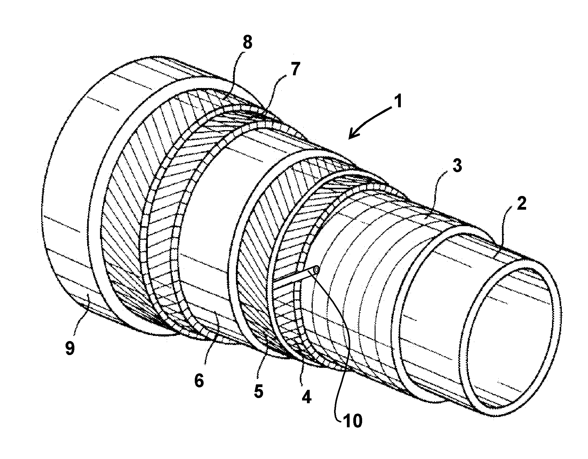
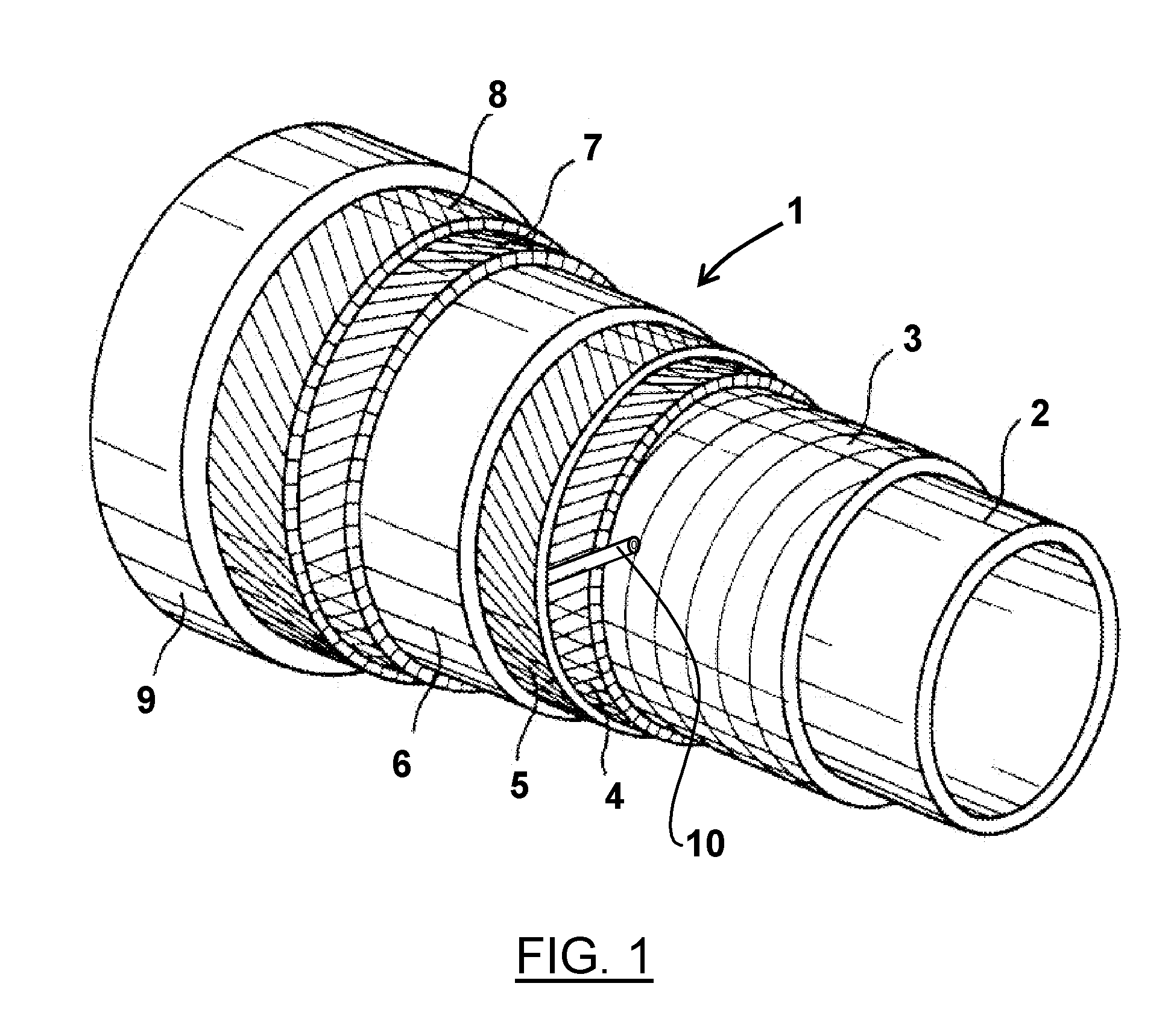
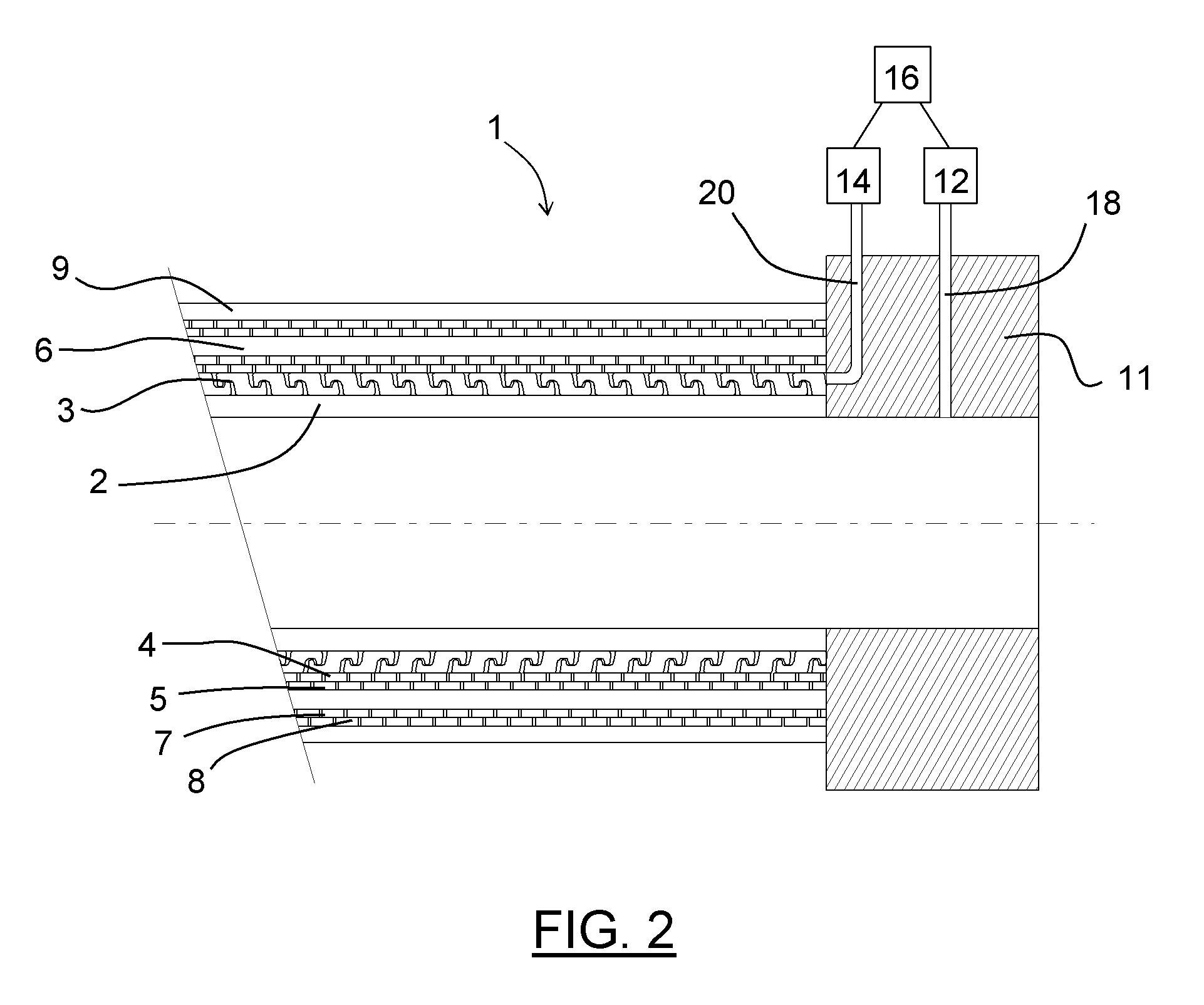
[0029]The flexible tubular pipe 1 of the invention is intended for offshore oil production and more particularly for transporting gaseous or two-phase hydrocarbons. It is of the unbonded type and meets the specifications defined in the normative document API 17J.

[0030]According to the embodiment of the invention illustrated in FIG. 1, the innermost element of the flexible tubular pipe 1 is an internal polymeric tube 2, which is generally manufactured by extrusion. It has the function of sealing the duct within which the fluid flows and of withstanding the radial pressure due to the internal pressure exerted by said fluid with the aid of the pressure vault 3. The internal wall of this tube is smooth, so that the pipe is referred to as a smooth-bore pipe.

[0031]The pressure vault 3 is formed by a short-pitch winding of an interlocking profiled metal wire. This profiled wire has for example a Z-shaped profile, commonly called a zeta profile, but other profiles may also be suitable, such...


PUM


Abstract

The invention relates to a flexible tubular duct for transporting gases under high pressure in the field of offshore oil exploitation. The duct is of the unlinked and smooth passageway type, and comprises from inside to outside an inner polymer tube, a pressure vault formed by the short-pitch rolling of at least one wire, a first inner pair of crossed traction armour plies, an intermediate polymer sleeve, a second outer pair of crossed traction armour plies and an outer polymer sleeve. The inner pair of traction armour plies is wound with a helical angle of less than 35° and the outer pair of traction armour plies is wound with a helical angle substantially equal to 55°.

Description

CROSS REFERENCE TO RELATED APPLICATION[0001]The present application is a 35 U.S.C. §§371 national phase conversion of PCT / FR2008 / 000589, filed Apr. 24, 2008, which claims priority of French Application No. 0703083, filed Apr. 27, 2007, incorporated by reference herein. The PCT International Application was published in the French language.BACKGROUND OF THE INVENTION[0002]The present invention relates to a flexible tubular pipe for transporting fluids (especially gaseous hydrocarbons) and to be used in an offshore oil production field. It relates more particularly to a flexible pipe of the unbonded type for transporting gaseous hydrocarbons or two-phase hydrocarbons containing a gaseous phase.[0003]These flexible pipes, which are formed from a combination of various superposed concentric layers, are called unbonded pipes whenever these layers have a certain freedom to move relative to one another. These flexible pipes comply with, among others, the recommendations of the normative do...

Claims


Application Information

Patent Timeline
IPC IPC(8): F16L11/10F16L11/22
CPCF16L11/083G01M3/2815F16L2201/30G01M3/2846G01M3/283F16L9/147F16L11/08
Inventor BINET, ERICCROME, TIM
Owner TECH FRANCE SA
Why Eureka
Try Eureka