

Vehicle drive system
a technology of drive system and drive shaft, which is applied in the direction of electric propulsion mounting, structural association, transportation and packaging, etc., can solve the problem that the demand above cannot be fully satisfied, and achieve the effect of improving mountability
- Summary
- Abstract
- Description
- Claims
- Application Information
AI Technical Summary
Benefits of technology
Problems solved by technology
Method used
Image

Examples
Embodiment Construction
[0028]In the following, embodiments of the present invention will be described. The same or corresponding portions are denoted by the same reference characters and description thereof may not be repeated.
[0029]In the embodiments described in the following, descriptions of numbers, amounts and the like are not intended to limit the scope of the invention unless otherwise specified. Further, in the embodiments below, each component is not always necessary, unless otherwise specified. When a plurality of embodiments are possible, it is naturally expected that structures of various embodiments are appropriately combined, unless otherwise specified.
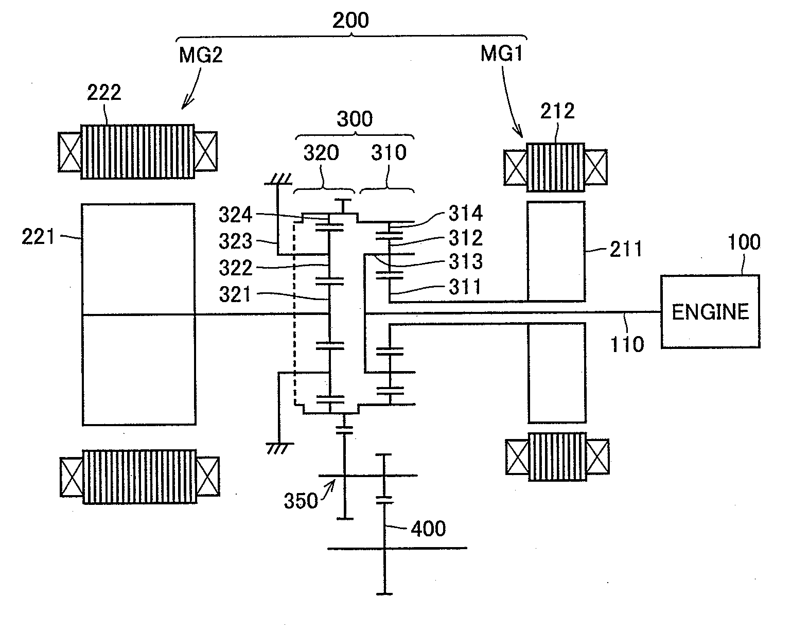
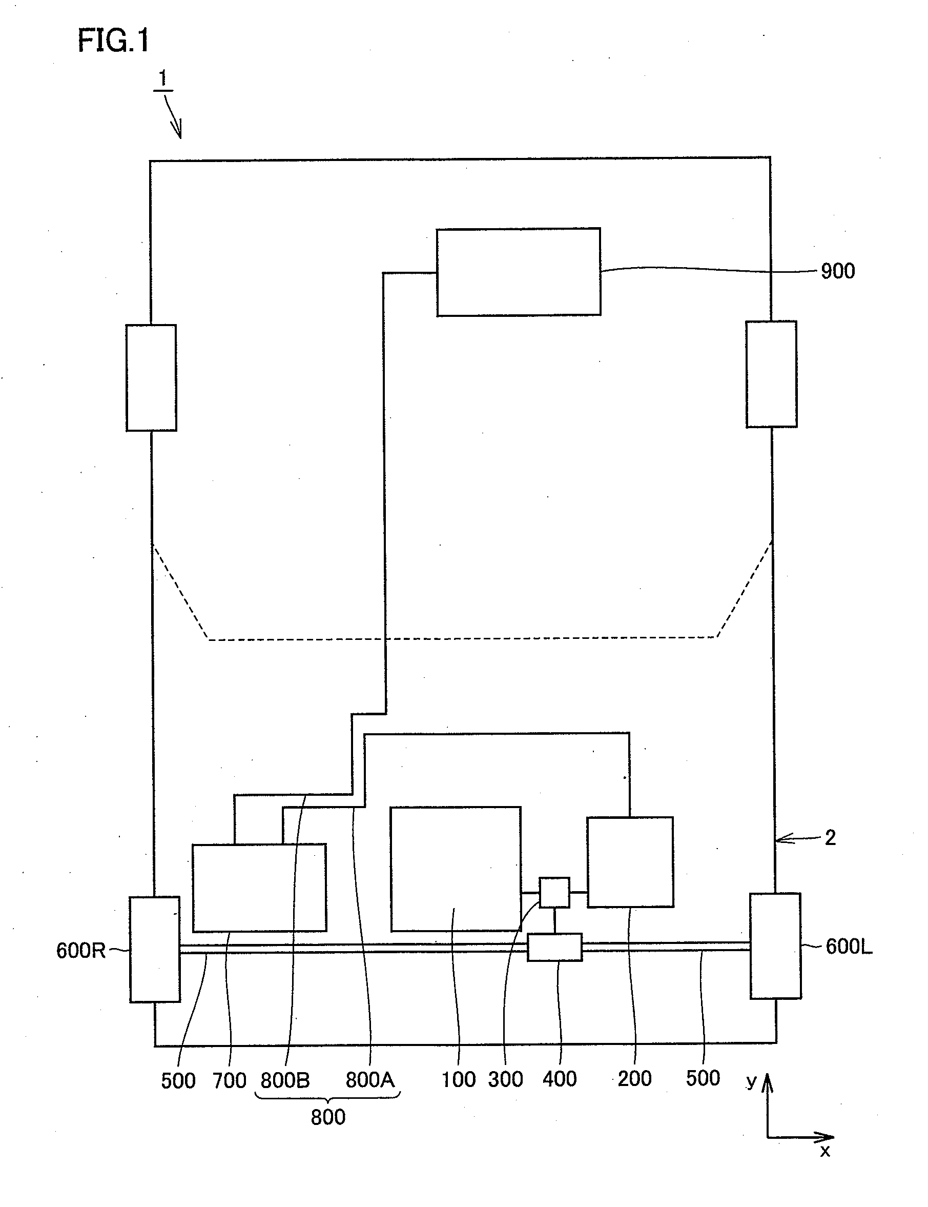
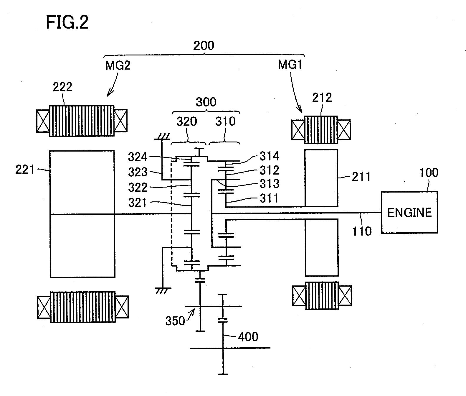
[0030]FIG. 1 is a schematic diagram showing a structure of a hybrid vehicle having the vehicle drive system in accordance with an embodiment of the present invention.
[0031]Referring to FIG. 1, a hybrid vehicle 1 includes an engine 100, a motor generator 200, a power split device 300, a differential mechanism 400, a drive shaft 500, driving whe...
PUM
 Abstract
Description
Claims
Application Information