Electro-optical device, and electronic apparatus having the same

a technology of electrooptical devices and electronic devices, which is applied in the direction of electric digital data processing, instruments, computing, etc., can solve the problems of reducing the frame portion of the display panel, wasting space in the frame portion of the scan line drive circuit, and affecting the balance of the display panel between the right and left frame portions, so as to prevent the degrade of display quality and reduce the frame portion

Inactive Publication Date: 2010-04-08
JAPAN DISPLAY WEST
View PDF11 Cites 19 Cited by
  • Summary
  • Abstract
  • Description
  • Claims
  • Application Information

AI Technical Summary

Benefits of technology

[0019]In a specific control process, after the first voltage is applied to the common electrode by the control circuit, the selection voltage is applied to the scan line and an image signal with a positive polarity is supplied to the data line. In addition, after the second voltage is applied to the common electrode by the control circuit, the selection voltage is applied to the scan line and an image signal with a negative polarity is supplied to the data line. With this configuration, the first voltage and the second voltage can be applied to the common electrodes alternately for each one horizontal line, and the image signal with the positive ...

Problems solved by technology

However, in a case where the COM divisional driving technique is used as in the liquid crystal display device described in JP-A-2008-33247, drivers for COM divisional driving are usually provided at both of right and left sides of a display panel, respectively in order to take a countermeasure for crosstalk, resulting in difficulty in reduction of the frame portion of the display panel.
However, the balance of the display panel between right and left frame portions is impaired...

Method used


Image

  • Electro-optical device, and electronic apparatus having the same
  • Electro-optical device, and electronic apparatus having the same
  • Electro-optical device, and electronic apparatus having the same

Examples


Embodiment Construction

[0029]The preferred embodiments according to the invention will be described with reference to the accompanying drawings.

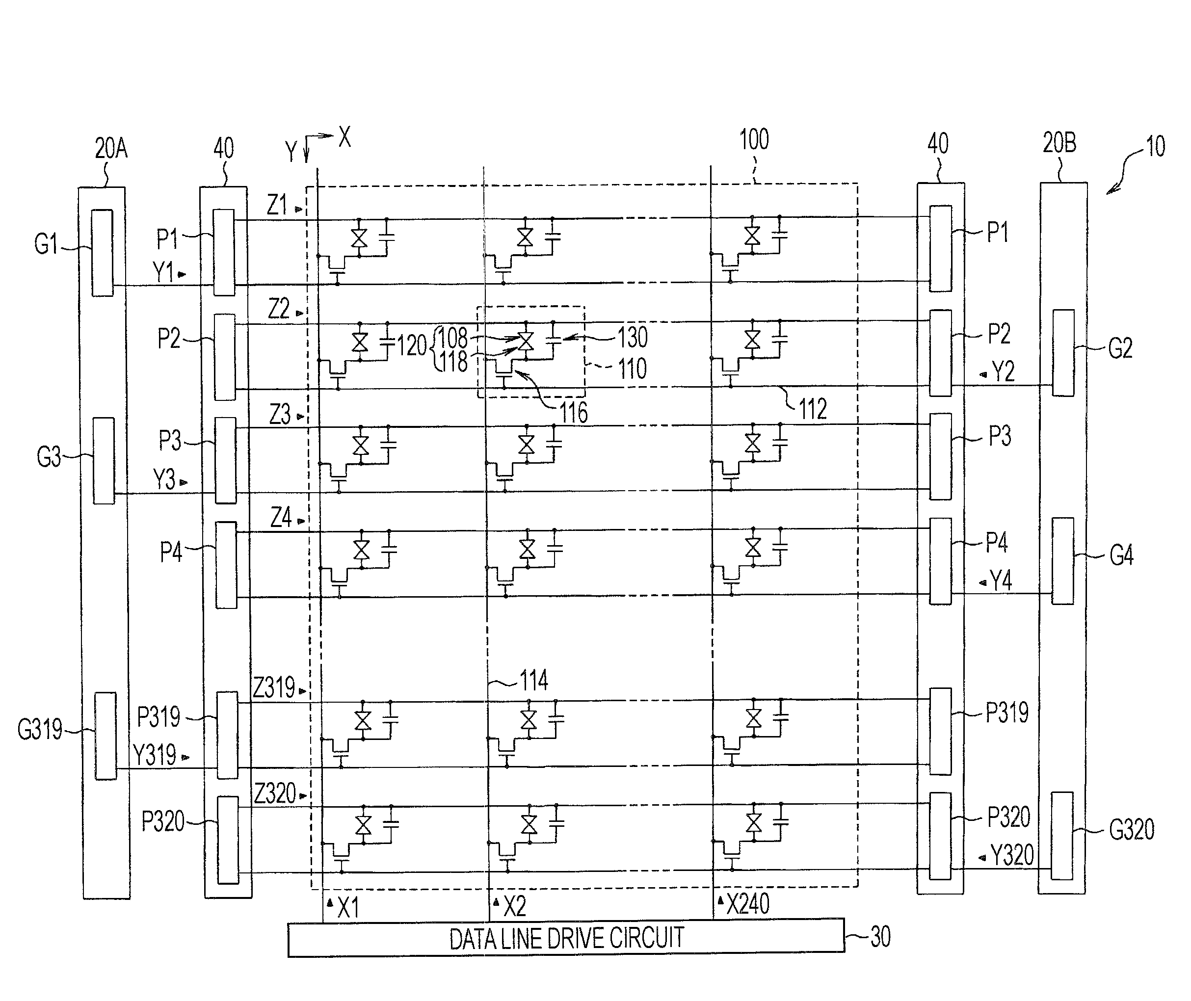
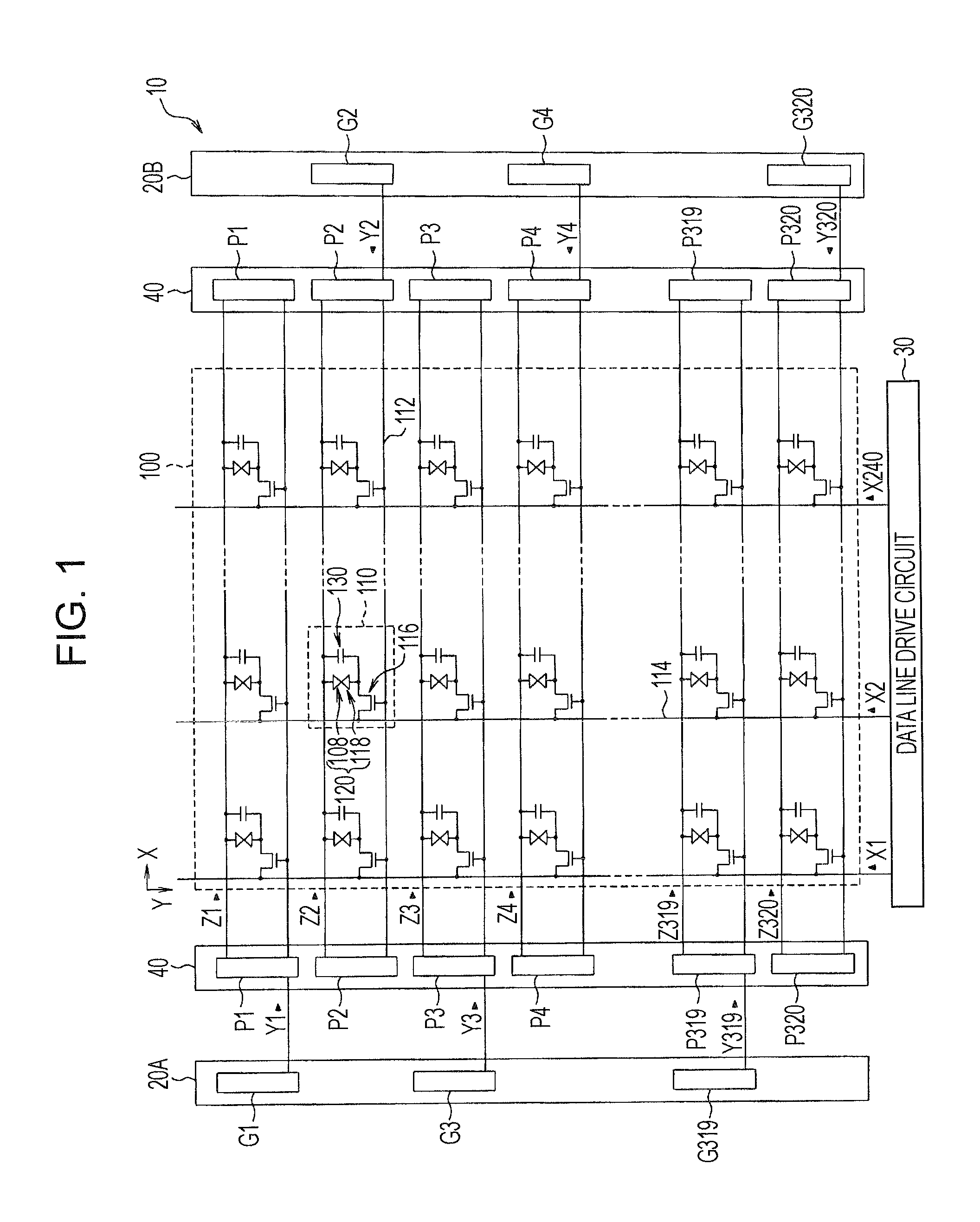
[0030]FIG. 1 is a block diagram showing a liquid crystal display device 10 as an electro-optical device according to a first embodiment of the invention. The liquid crystal display device 10 is equipped with a liquid crystal panel having an active matrix type thin-film transistor (TFT). As shown in FIG. 1, the liquid crystal display device 10 has a display region 100, and scan line drive circuits 20A and 20B, a data line drive circuit 30 and a common electrode drive circuit 40 are arranged at a peripheral of the display region 100. The liquid crystal panel is constituted in such a manner that an element substrate and an opposing substrate are stuck to each other so as to cause electrode formed faces to be opposed to each other with a predetermined gap therebetween and a liquid crystal is enclosed in the gap (not shown).

[0031]In the display region 100 provided in t...


PUM


Abstract

An electro-optical device includes a plurality of scan lines, a plurality of data lines, a plurality of pixels respectively provided at intersections between the plurality of scan lines and the plurality of data lines, and a scan line drive circuit that applies a selection voltage to the scan lines in a predetermined sequence. The scan line drive circuit is composed of a first scan line drive circuit disposed at one side of the scan line and a second scan line drive circuit disposed at the other side of the scan line. The first scan line drive circuit applies the selection voltage to some of the scan lines, and the second scan line drive circuit applies the selection voltage to the remaining scan lines.

Description

BACKGROUND[0001]1. Technical Field[0002]The present invention relates to an electro-optical device and an electronic apparatus having the electro-optical device.[0003]2. Related Art[0004]Heretofore, an electro-optical device such as a liquid crystal display device has been widely known as a display device for displaying an image. Such a liquid crystal display device has an element substrate, an opposing substrate disposed so as to face the element substrate, and a liquid crystal sandwiched between the element substrate and the opposing substrate. A liquid crystal display similar to the above is known that includes a control circuit that alternately applies a voltage VCOMH and a voltage VCOMH to a common electrode, a scan line drive circuit that sequentially applies a selection voltage to a plurality of scan lines and a data line drive circuit that alternately supplies an image signal with a positive polarity and an image signal with a negative polarity to a plurality of data lines w...

Claims


Application Information

Patent Timeline
IPC IPC(8): G09G5/00
CPCG09G2320/0247G09G3/3677
Inventor KATO, TOMOTOSHI
Owner JAPAN DISPLAY WEST
Why Eureka
Try Eureka