Switching power supply apparatus

a power supply apparatus and switch technology, applied in the direction of electric variable regulation, process and machine control, instruments, etc., can solve the problems of difficult linear signal transmission, inability to realistically and realistically achieve the type of digital control circuit, etc., and achieve the effect of reducing size and cos

Inactive Publication Date: 2010-04-15
MURATA MFG CO LTD
View PDF9 Cites 19 Cited by
  • Summary
  • Abstract
  • Description
  • Claims
  • Application Information

AI Technical Summary

Benefits of technology

[0015]To overcome the problems described above, preferred embodiments of the present invention provide a switching power supply apparatus which has a significantly reduced size and cost.

Problems solved by technology

Accordingly, this type of digital control circuit is not realistic or feasible in terms of cost and space.
Furthermore, when the isolated unit is used for signal transmission, it is difficult to transmit linear signals.

Method used


Image

  • Switching power supply apparatus
  • Switching power supply apparatus
  • Switching power supply apparatus

Examples


first preferred embodiment

[0064]A switching power supply apparatus according to a first preferred embodiment of the present invention will be described with reference to FIGS. 2 to 8.

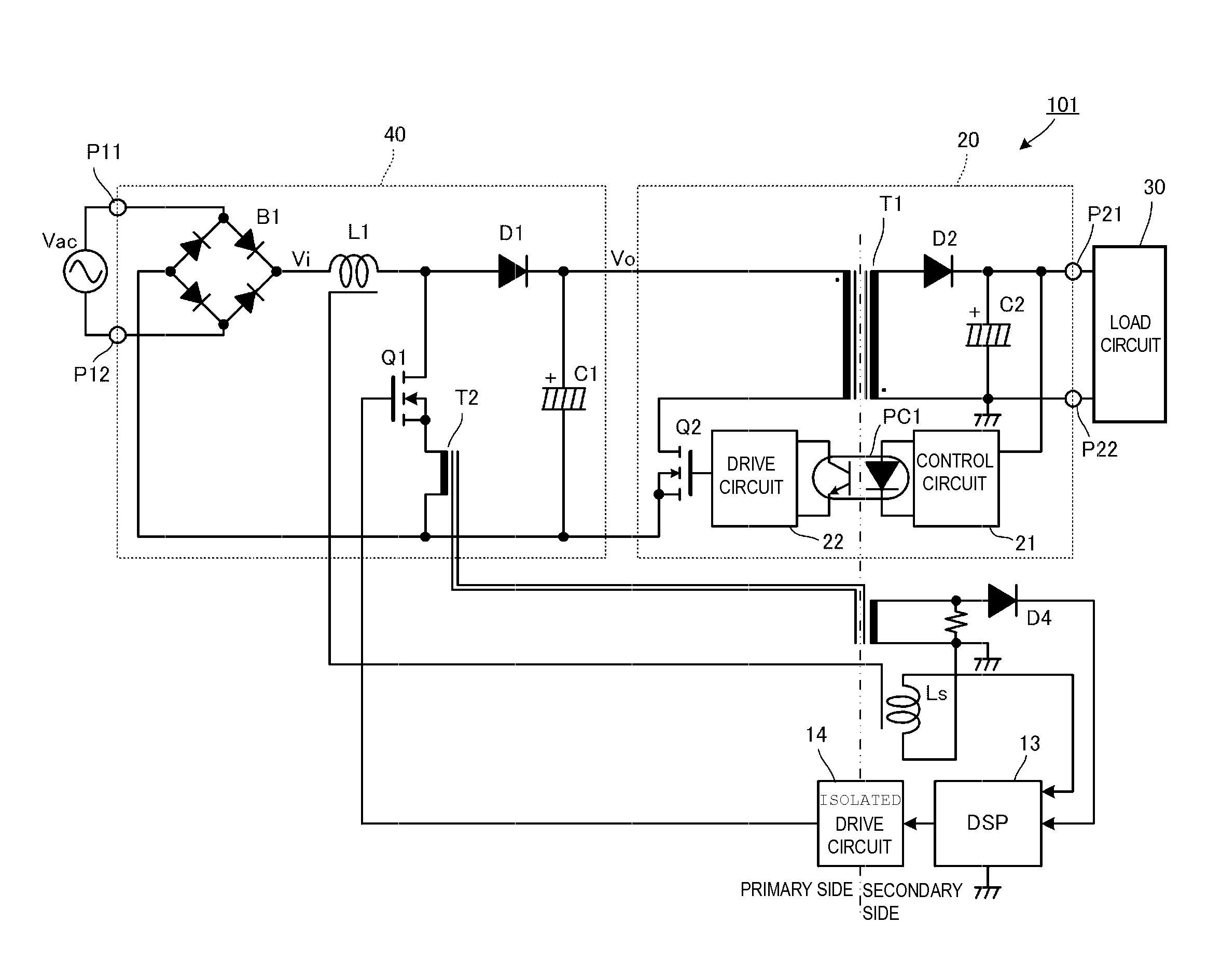
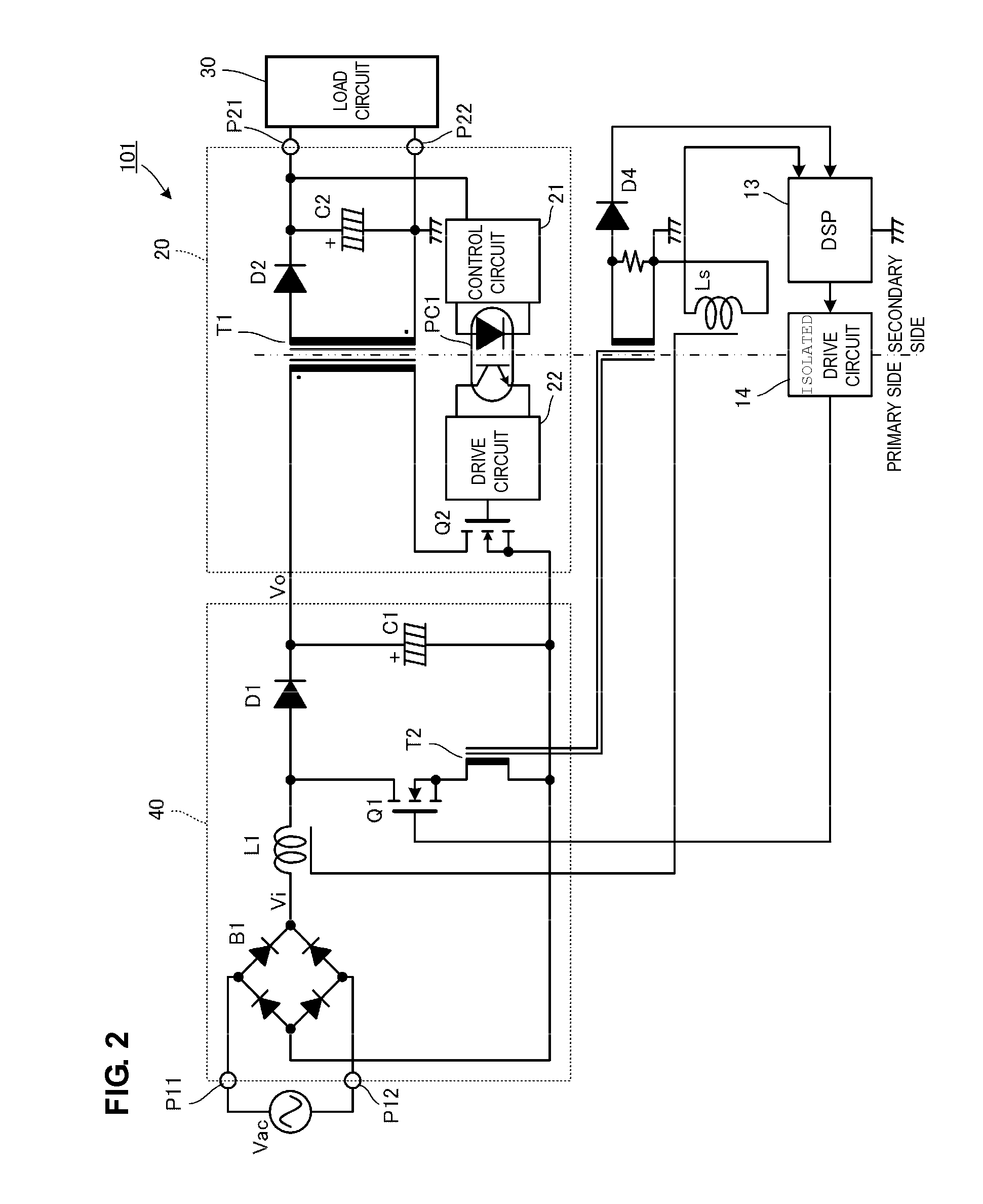
[0065]FIG. 2 is a circuit diagram illustrating a switching power supply apparatus 101 according to the first preferred embodiment. Unlike the circuit in the related art shown in FIG. 1, a digital signal processing circuit 13 defining a “digital control circuit” is included in a secondary side of an isolated DC-DC converter 20. The digital signal processing circuit 13 is preferably configured as a DSP, for example.

[0066]A primary side of a current transformer T2 is connected to a drain current path of a switching element Q1 included in a PFC converter 40. A secondary side of the current transformer T2 is connected to the digital signal processing circuit 13. Note that a diode D4 connected to the secondary side of the current transformer T2 is used to detect a current supplied between a drain and a source while a zero line is not ...

second preferred embodiment

[0095]FIG. 9 is a diagram illustrating a configuration of an inductor L1 and in the vicinity thereof included in a switching power supply apparatus according to a second preferred embodiment of the present invention. Other configurations are substantially the same as those shown in FIG. 2.

[0096]In the second preferred embodiment, a method for detecting a voltage Vo output from a PFC converter 40 will be described. Note that, in an example shown in FIG. 9, a pulse transformer T4 is disposed in the inductor L1 so that the output voltage Vo is obtained based on a voltage Vb on a secondary side of the pulse transformer T4.

[0097]Assuming that a winding ratio of a primary winding to a secondary winding of the pulse transformer T4 is denoted by np:ns, the voltage output from the pulse transformer T4 when a switching element Q1 is in an on state is also represented by Expression (3), and the voltage Vo output from the PFC converter is also calculated on the basis of Expression (5).

third preferred embodiment

[0098]FIG. 10 is a diagram illustrating a method for detecting a voltage input to a PFC converter and a voltage output from the PFC converter included in a switching power supply apparatus according to a third preferred embodiment of the present invention. A circuit configuration is substantially the same as that shown in FIG. 2.

[0099]In the third preferred embodiment, a voltage Vo output from a PFC converter 40 is detected based on an inclination of a current IL supplied to an inductor L1 shown in FIG. 10.

[0100]Here, when an inclination of the current IL when a switching element Q1 is in an on state (Ton) is denoted by ΔILon, an inclination in an off state (Toff) is denoted by ΔILoff, an input voltage is denoted by Vi, an output voltage is denoted by Vo, and an inductance of the inductor L1 is denoted by L, Expressions (7) and (8) below are obtained.

ΔILon=(Vi / L)Ton   (7)

ΔILOff={(Vo−Vi) / L}Toff   (8)

[0101]The values ΔILon, and ΔILOff can be obtained using drain currents IDb and IDp, ...


PUM


Abstract

A digital signal processing circuit which performs average current control is disposed on a secondary side of a transformer of an isolated DC-DC converter, and a switching control signal output from the digital signal processing circuit is transmitted to a switching element included in a power factor correction converter through an isolated drive circuit. The digital signal processing circuit obtains an average value of currents supplied to an inductor in accordance with a voltage output from a bias winding of the inductor or an output from a secondary side of a current transformer which detects a drain current of the switching element. Furthermore, the average value of the currents corresponds to a waveform (full-wave rectification sine wave) of an input voltage Vi.

Description

BACKGROUND OF THE INVENTION[0001]1. Field of the Invention[0002]The present invention relates to an AC-DC converter which receives an alternate current power and outputs a direct current voltage, and particularly to a switching power supply apparatus including a Power Factor Correction (“PFC”) converter which improves a power factor.[0003]2. Description of the Related Art[0004]Conventionally, harmonic current restriction is in effect in various categories divided in accordance with usage and input power based on “Japanese Guidelines for Reduction of Harmonic Emission Caused By Electrical and Electronic Equipment for Household and General Use” in Japan, and similarly, the harmonic current is restricted in European countries and various other countries around the world. Therefore, a PFC converter is added to power supply apparatuses for typical home electronics so as to suppress the harmonic current (see, for example, Japanese Unexamined Patent Application Publication No. 5-191976).[0...

Claims


Application Information

Patent Timeline
Patent Type & Authority Applications(United States)
IPC IPC(8): H02M3/335
CPCH02M1/4225H02M3/28Y02B70/126H02M2001/008H02M2001/0006Y02B70/10H02M1/0006H02M1/008
Inventor UNO, YOSHIYUKITOKUGAWA, TOMOKUNIHOSOTANI, TATSUYA
Owner MURATA MFG CO LTD
Why Eureka
Try Eureka