Optical Transceiver module

a transceiver module and optical technology, applied in the field of optical transceivers, can solve the problems of occupying space for optical components and disadvantages of axial alignmen

Inactive Publication Date: 2010-04-15
OKI ELECTRIC IND CO LTD
View PDF4 Cites 60 Cited by
  • Summary
  • Abstract
  • Description
  • Claims
  • Application Information

AI Technical Summary

Benefits of technology

[0008]An object of the present invention is to provide an optical transceiver module with a reduced size.

Problems solved by technology

A disadvantage of this type of ONU is that the optical components take up space.
The need for axial alignment is also a disadvantage.

Method used


Image

  • Optical Transceiver module
  • Optical Transceiver module
  • Optical Transceiver module

Examples


first embodiment

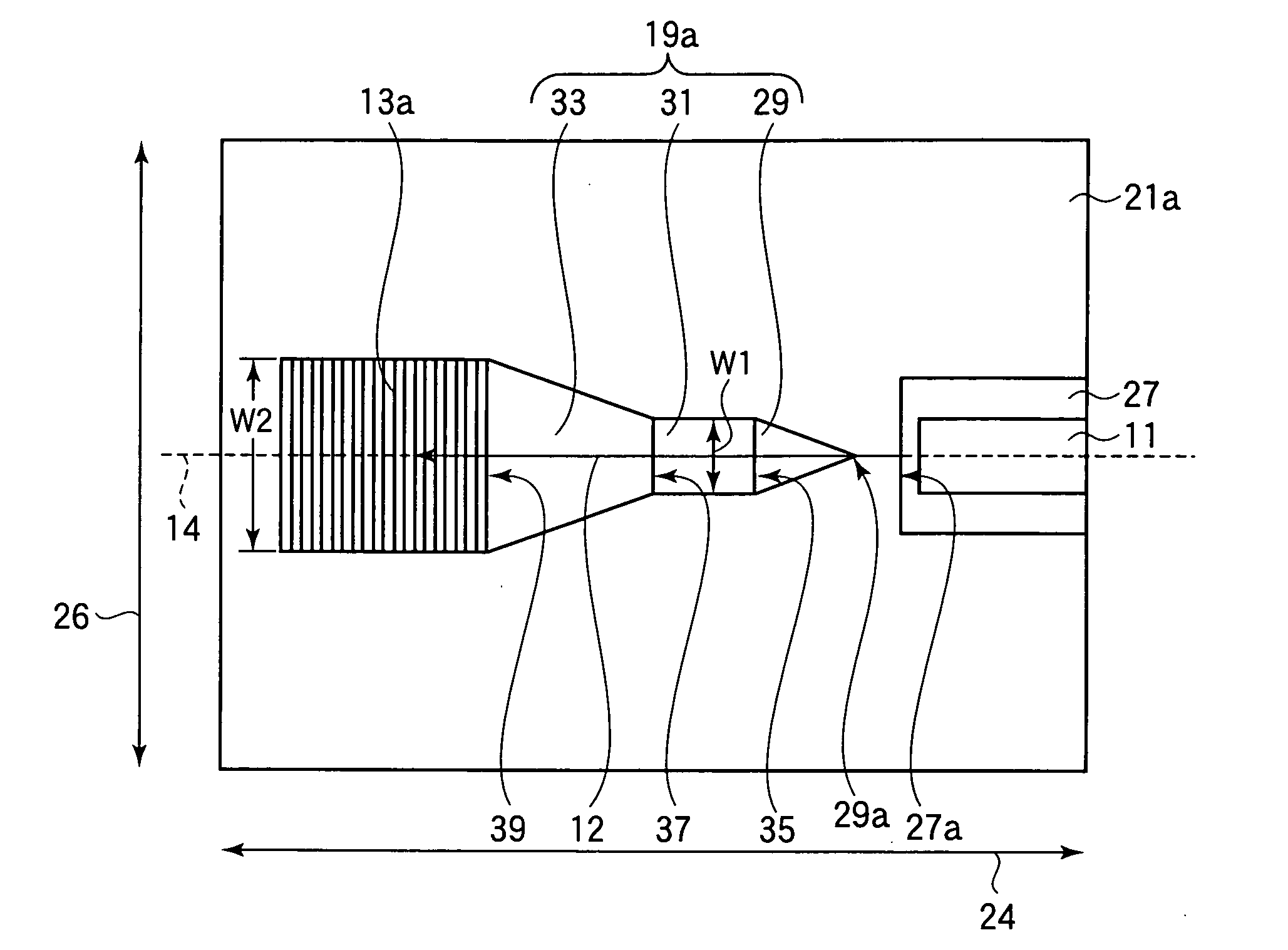
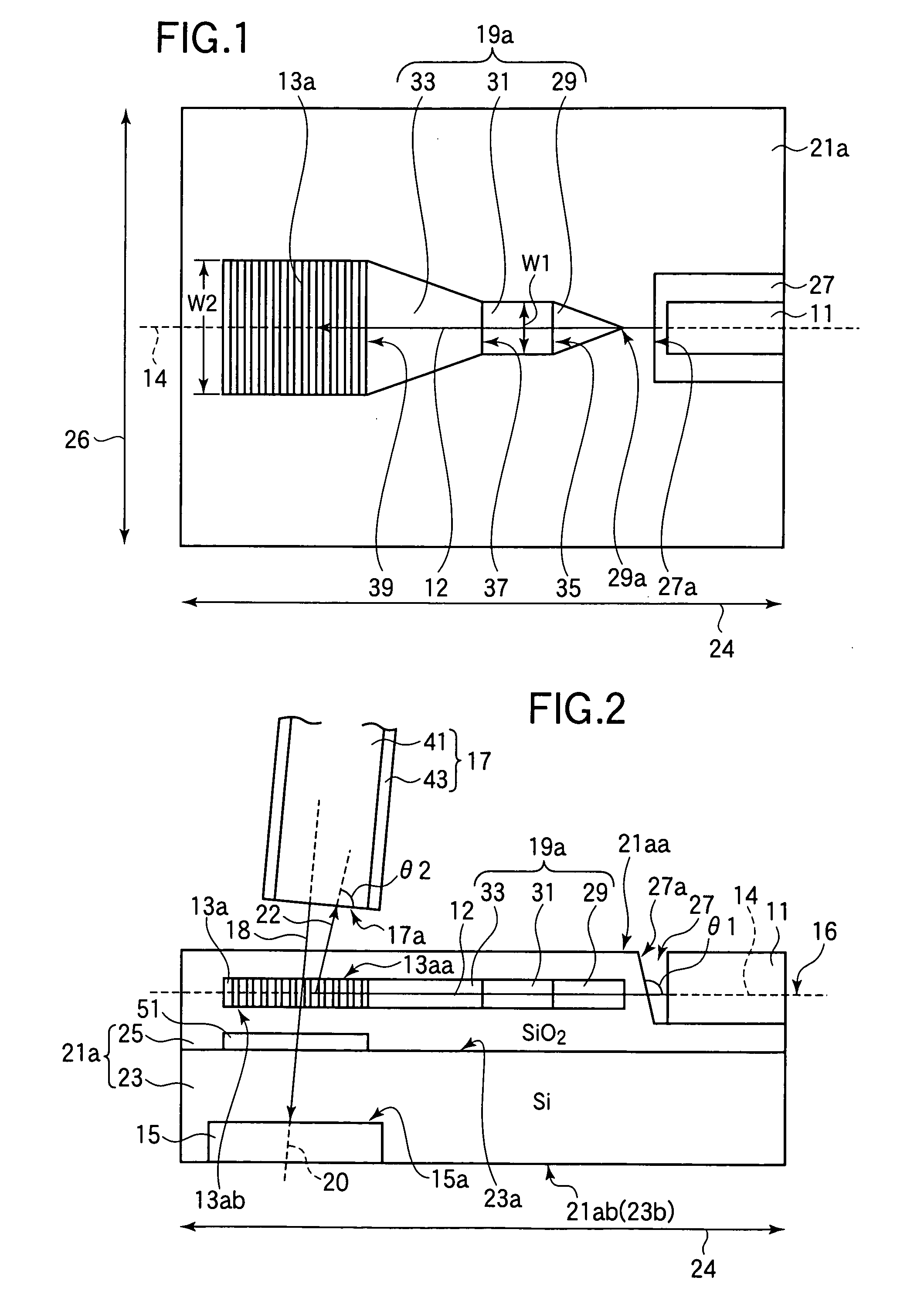
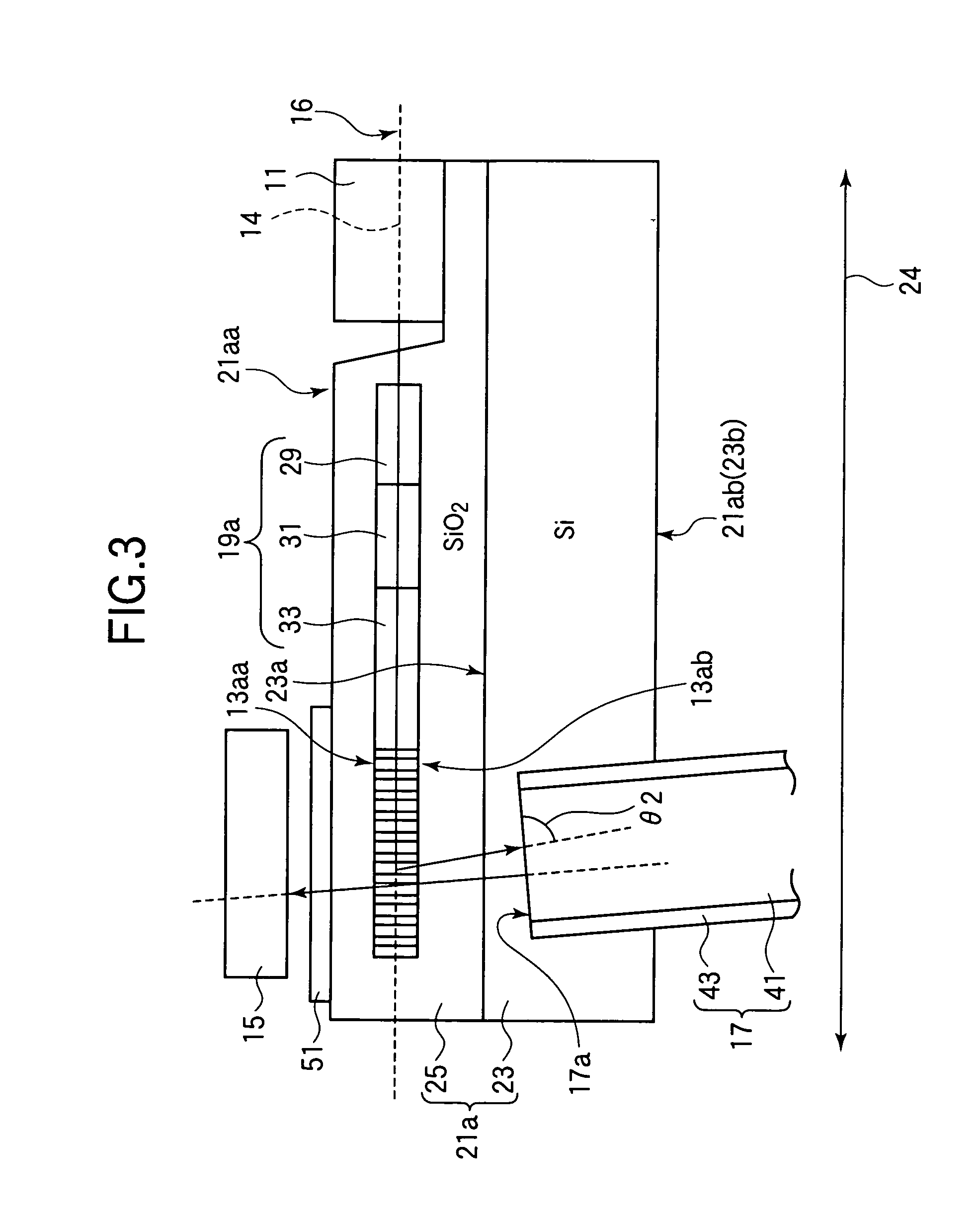
[0024]Referring to FIG. 1, the optical transceiver module in the first embodiment has a semiconductor laser 11, a grating coupler 13a, and an optical waveguide 19a, which are formed in or mounted on a substrate 21a with a longitudinal direction or first optical axis direction 24 and a width direction 26.

[0025]The semiconductor laser 11 functions as the transmitter in the optical transceiver module by generating outgoing light, referred to below as the upstream optical signal 12. The wavelength of the upstream optical signal 12 is, for example, about 1.31 micrometers (1.31 μm). The semiconductor laser 11 is mounted in a recess 27 in the substrate 21a.

[0026]The grating coupler 13a is a rectangular plane waveguide with a series of grooves that diffract the upstream optical signal 12.

[0027]The optical waveguide 19a extends from the grating coupler 13a toward the semiconductor laser 11 along a first optical axis 14, forming a path that guides the upstream optical signal 12 from the semi...

second embodiment

[0053]An optical transceiver module according to a second embodiment will be described with reference to FIGS. 6 and 7.

[0054]The optical transceiver module in the second embodiment differs from the optical transceiver module in the first embodiment mainly in that the semiconductor laser is integrated with the optical waveguide and grating coupler to reduce the length of the optical transceiver module. The other transceiver components and their functions are the same as in the first embodiment; repeated descriptions will be omitted.

[0055]This optical transceiver module is also used to transmit optical signals to and receive optical signals from an external optical system (optical fiber) 17.

[0056]Referring to FIG. 6, the optical transceiver module in the second embodiment has a grating coupler 13b similar to the grating coupler 13a in the first embodiment and an optical waveguide 57, aligned in the first optical axis direction 24 of a base 21b. The optical transceiver module in the se...


PUM


Abstract

An optical transceiver module includes a semiconductor laser that emits light along a first optical axis. A grating coupler, located in a plane including the first optical axis, diffracts the emitted light out of the plane and into an external optical system. A photodetector receives incoming light from the external optical system on a second optical axis that passes through the grating coupler at an angle to the plane. The photodetector can be placed parallel to the plane, directly above or below the grating coupler, to create an extremely compact optical transceiver module.

Description

BACKGROUND OF THE INVENTION[0001]1. Field of the Invention[0002]The present invention relates to a transceiver module.[0003]2. Description of the Related Art[0004]Conventional fiber-to-the-home (FTTH) systems use a single optical fiber for both upstream optical transmission from the subscriber to the central office and downstream optical transmission from the central office to the subscriber. Different wavelengths are used for upstream and downstream transmission, so the optical transceiver modules in an FTTH system must include devices for coupling optical signals with different wavelengths into and out of the optical fiber.[0005]The transceiver module used at the subscriber terminal is referred to as an optical network unit (ONU). The ONUs currently available typically include a laser diode transmitting device, a photodiode receiving device, and optical components with spatially aligned optical axes. A disadvantage of this type of ONU is that the optical components take up space. ...

Claims


Application Information

Patent Timeline
Patent Type & Authority Applications(United States)
IPC IPC(8): G02B6/12G02B6/34G02B6/32
CPCG02B6/102G02B6/1228G02B6/4246G02B6/4214G02B6/4215G02B6/124
Inventor OKAYAMA, HIDEAKI
Owner OKI ELECTRIC IND CO LTD
Why Eureka
Try Eureka