
Autothermal and partial oxidation reformer-based fuel processor, method for improving catalyst function in autothermal and partial oxidation reformer-based processors

a technology of autothermal and partial oxidation reformer and fuel processor, which is applied in the direction of liquid-gas reaction of thin-film type, gas-gas reaction process, combustible gas production, etc., can solve the problems of low average temperature and therefore lower hydrogen yield, and achieve the effect of discharging thermal energy generated

Inactive Publication Date: 2010-04-22
UCHICAGO ARGONNE LLC
View PDF1 Cites 4 Cited by
  • Summary
  • Abstract
  • Description
  • Claims
  • Application Information

AI Technical Summary

Benefits of technology

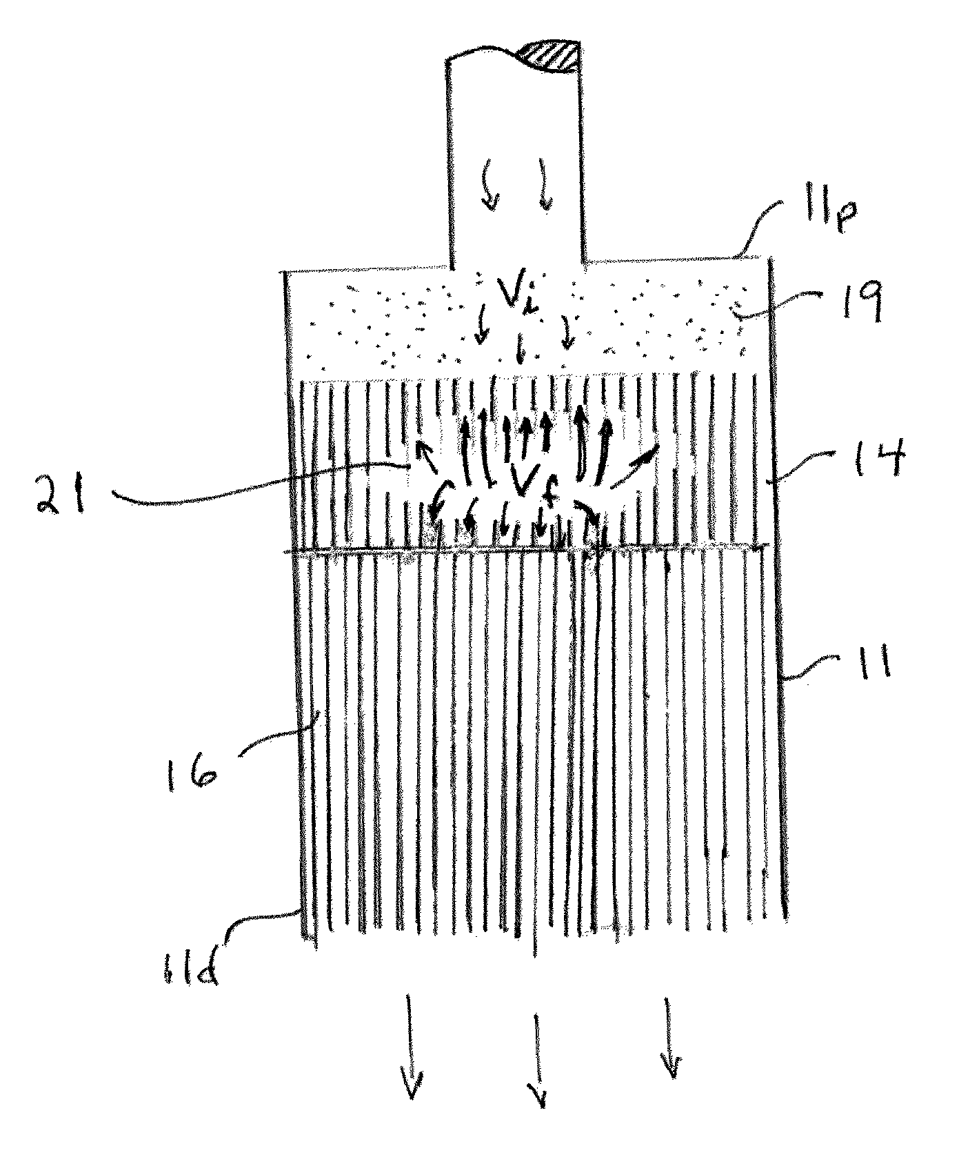
[0015]Another object of the present invention is to provide a system for vastly increasing the catalyst life in autothermal and partial oxidation reformer-based processors. A feature of the invention is the physical separation of different catalysts in the system. An advantage of the invention is that the different catalysts are each heated to their optimum operating temperature to concomitantly facilitate chemical conversions.
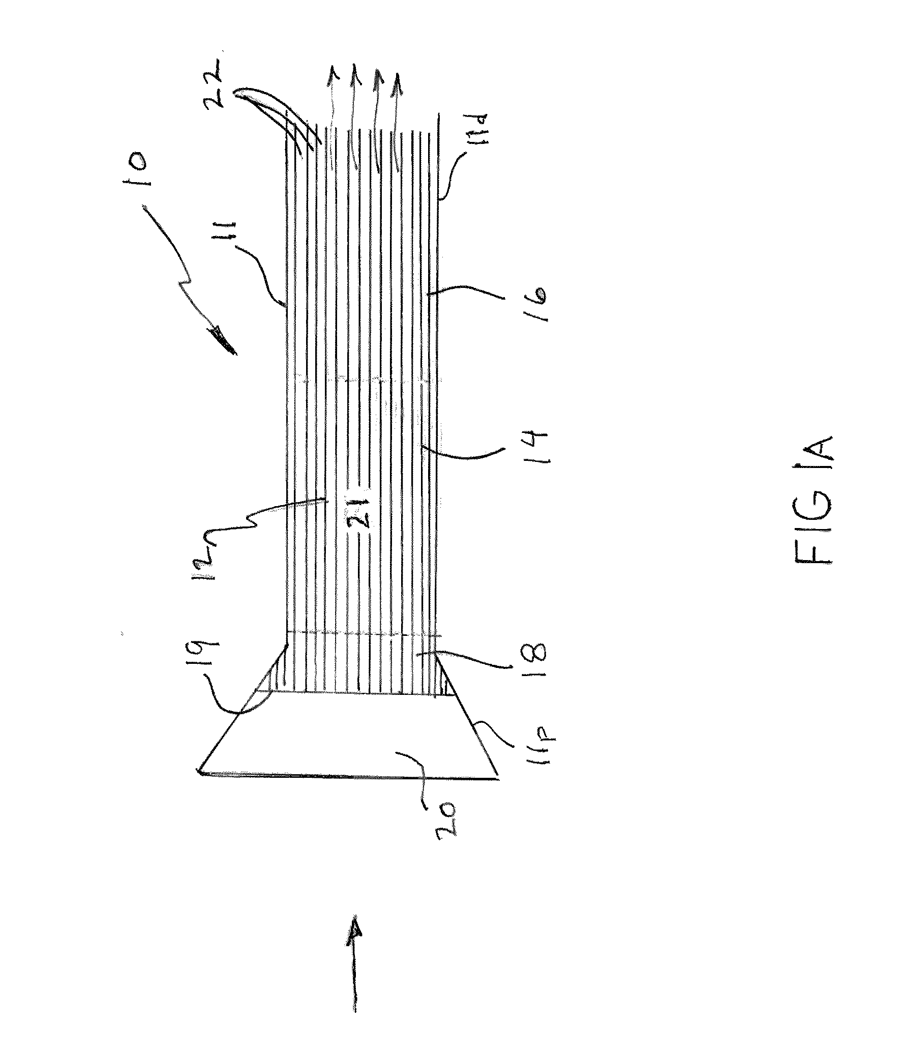
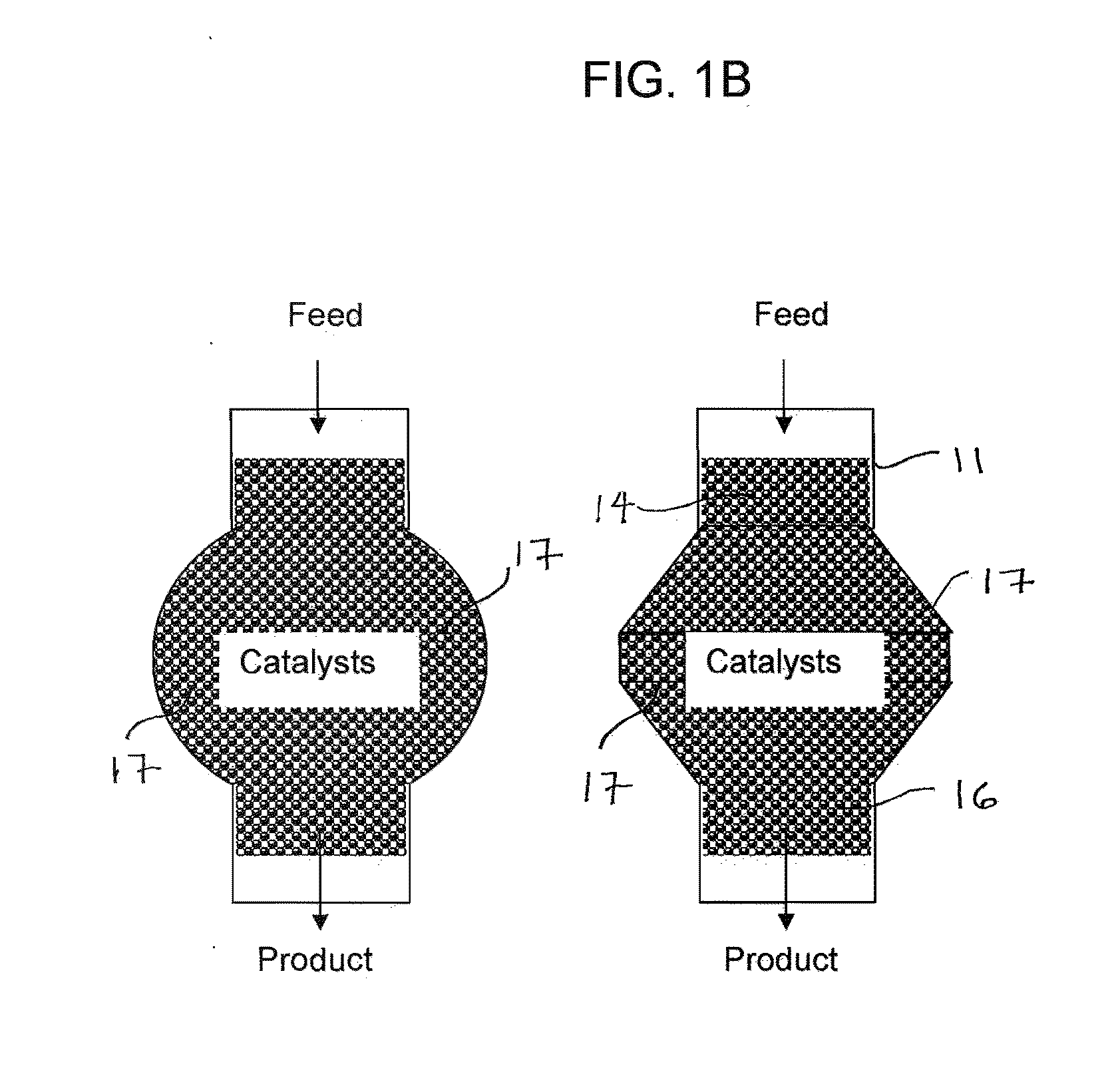
[0016]Yet another object of the present invention is to provide a partial oxidation or an autothermal reformer based system which comprises three temperature zones. A feature of the invention is a porous catalyst support structure that extends throughout the zones, such that catalysts used in the system all contact the structure so as to be supported by the structure. An advantage of the invention is that the structure provides a conduit for both heat and fluids to traverse through the zones, thereby establishing fluid communication between the temperature zones. This structure provides a means for dissipating thermal energy generated in oxygen-rich upstream conversions so as to protect more heat sensitive, downstream noble-metal catalysts.
[0017]Briefly, the invention provides a fuel processor comprising a linear flow structure having an upstream portion and a downstream portion; a first catalyst supported at the upstream portion; and a second catalyst supported at the downstream portion, wherein the first catalyst is in fluid communication with the second catalyst.
[0018]Also provided is a method for reforming fuel, the method comprising: contacting the fuel to an oxidation catalyst so as to partially oxidize the fuel and generate heat; warming incoming fuel with the heat while simultaneously warming a reforming catalyst with the heat; and reacting the partially oxidized fuel with steam in the presence of the reforming catalyst.

Problems solved by technology

While reducing the air in the mixture feeds (i.e., making the fuel mix richer) will minimize peak temperatures, it also leads to a lower average temperature and therefore to lower hydrogen yields.
However, this has proved counterproductive, inasmuch as the air reacts with any hydrogen produced instead of being utilized to facilitate oxidation of the carbon in the unconverted hydrocarbon.

Method used


Image

  • Autothermal and partial oxidation reformer-based fuel processor, method for improving catalyst function in autothermal and partial oxidation reformer-based processors
  • Autothermal and partial oxidation reformer-based fuel processor, method for improving catalyst function in autothermal and partial oxidation reformer-based processors
  • Autothermal and partial oxidation reformer-based fuel processor, method for improving catalyst function in autothermal and partial oxidation reformer-based processors

Examples


case b

[0058 shows the scenario where ignition occurs on the Rh-catalyst section (i.e., the downstream portion 16). The exit conversion after the Rh-catalyst is similar between case A and B, but the Rh-catalyst in case B peaks at 970° C., which will damage the reforming catalyst.

[0059]In Case C, ignition occurs again on the Rh-catalyst section but the air-to-fuel ratio is decreased to 0.36 from 0.53 to reduce the peak temperature. The peak temperature of 840° C. seen by the Rh catalyst is the same as in Case A, but because of the lower average bed temperature in Case C, the conversion of the fuel is much lower (80 percent compared to 98.6 percent in Case A).

[0060]FIG. 2 also shows the three portions of the catalyst support, as discussed supra. Specifically, the uncoated portion 18 of the catalyst is designated as “blank foam” in the figure. The oxidation or upstream portion 14 of the catalyst support is designated as “hexa-aluminate.” The reforming or downstream portion 16 of the catalyst ...


PUM

PropertyMeasurementUnit
temperatureaaaaaaaaaa
lengthaaaaaaaaaa
temperatureaaaaaaaaaa

Abstract

The invention provides a fuel processor comprising a linear flow structure having an upstream portion and a downstream portion; a first catalyst supported at the upstream portion; and a second catalyst supported at the downstream portion, wherein the first catalyst is in fluid communication with the second catalyst. Also provided is a method for reforming fuel, the method comprising contacting the fuel to an oxidation catalyst so as to partially oxidize the fuel and generate heat; warming incoming fuel with the heat while simultaneously warming a reforming catalyst with the heat; and reacting the partially oxidized fuel with steam using the reforming catalyst.

Description

PRIORITY[0001]This Utility Patent Application claims the benefits of U.S. Provisional Patent Application No. 61 / 106,888, filed on Oct. 20, 2008.CONTRACTUAL ORIGIN OF THE INVENTION[0002]The U.S. Government has rights in this invention pursuant to Contract No. DE-AC02-06CH11357 between the U.S. Department of Energy and the University of Chicago representing Argonne National Laboratory.BACKGROUND OF THE INVENTION[0003]1. Field of the Invention[0004]The present invention relates to partial oxidation or autothermal reforming of fuel, and more specifically, the invention relates to segmented catalyst systems for use in reforming of fuel for use in fuel cells.[0005]2. Background of the Invention[0006]Partial oxidation and autothermal reformers convert hydrocarbon and oxygenated fuels into hydrogen and carbon oxides which can be used in fuel cell applications; particularly fuel cell applications constrained by weight and volume, or which require frequent starts and stops, and have to respon...

Claims


Application Information

Patent Timeline
Patent Type & Authority Applications(United States)
IPC IPC(8): C10J3/00
CPCC01B3/382C01B2203/0244C10J1/20C01B2203/1047C01B2203/1082C01B2203/1041
Inventor AHMED, SHABBIRPAPADIAS, DIONISSIOS D.LEE, SHELDON H.D.AHLUWALIA, RAJESH K.
Owner UCHICAGO ARGONNE LLC
Learn More