
Process for fabricating integral plastic faucet member and finished product thereof

a technology of plastic faucets and components, applied in the field of faucet components, can solve the problems of excessive processing time, low product yield, low efficiency, etc., and achieve the effects of reducing transportation costs, reducing production efficiency and product quality, and reducing production costs

Active Publication Date: 2010-04-22
GLOBE UNION INDAL
View PDF7 Cites 32 Cited by
  • Summary
  • Abstract
  • Description
  • Claims
  • Application Information

AI Technical Summary

Benefits of technology

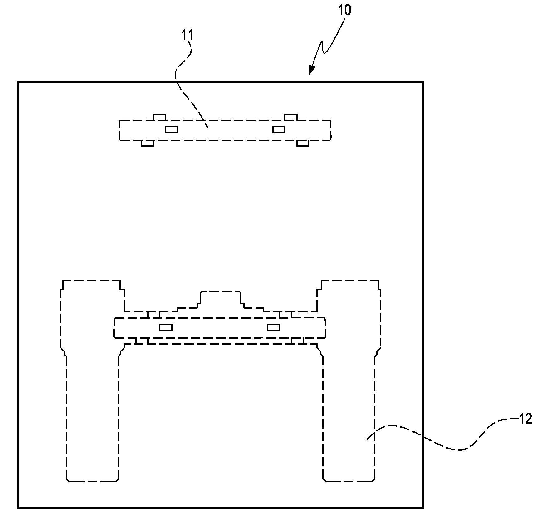
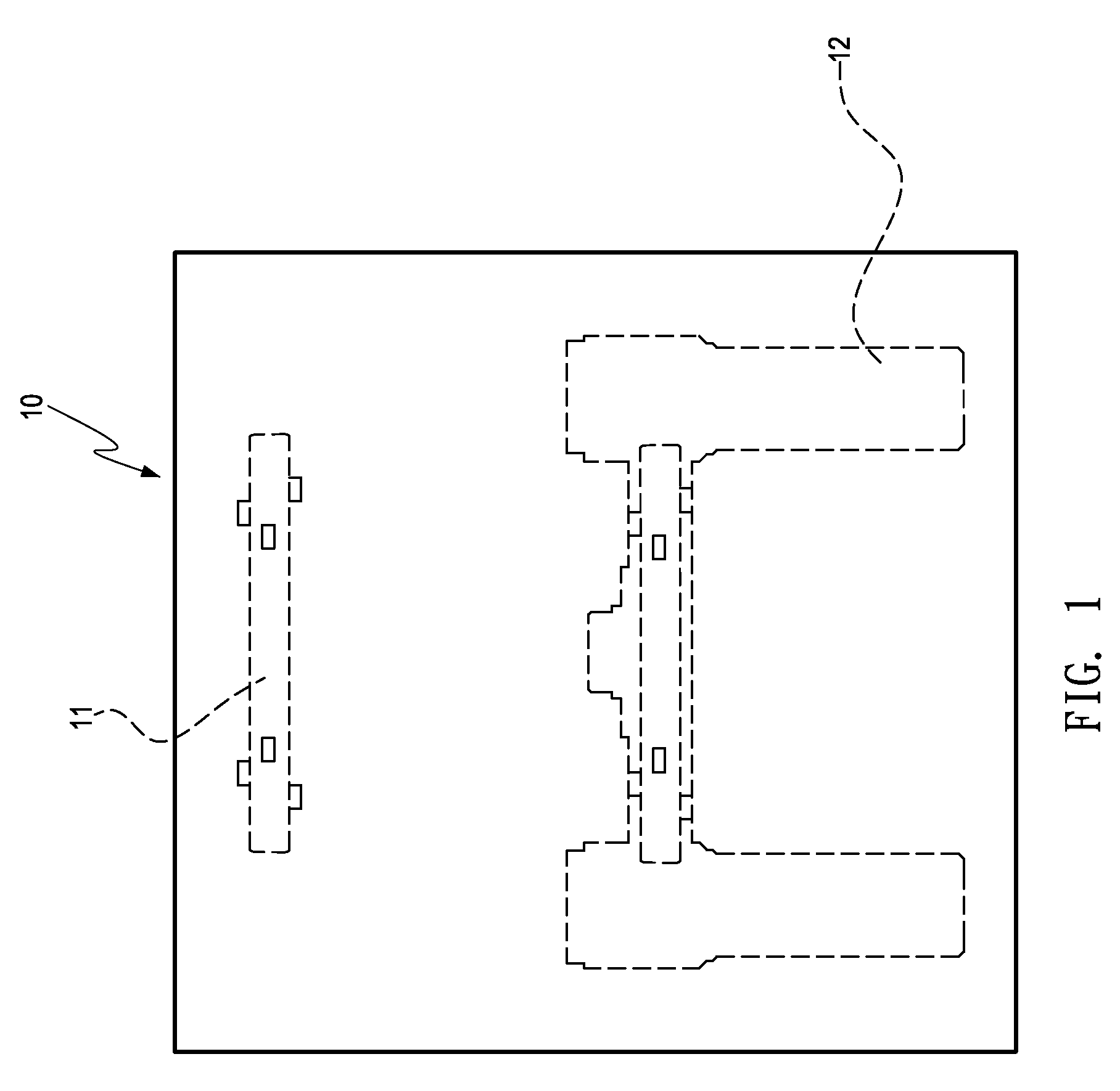
[0008]The process provided in the present invention only needs two plastic injection molding steps and a step of taking out and positioning the molded first part, so the whole process is quite simple. Therefore, the production efficiency and product quality can be greatly improved. Meanwhile, the weight of the product is also low, which greatly reduces the transportation cost. Since the second part may be wrapped around the first part and integrally molded with the first part, a better structural strength is achieved. Moreover, since the assembly does not need too many labor forces, the production efficiency and product quality is also be improved, and the labor cost of assembly is reduced.

Problems solved by technology

Therefore, the whole process is complicated and time-consuming, resulting in an excessively long processing time, a low efficiency, and a low product yield.
In addition, the fast wearing of cutting tools required by machining also increase the production and fabrication costs.
Meanwhile, if the cutting tools are not properly maintained or replaced, the precision of finished size may also be affected, resulting in degradation of the product quality.
Moreover, the copper used in copper casting is expensive, and also has a high specific weight, which correspondingly increases the whole transportation cost.
Thus, such a process is not cost effective.
However, such a process has its own disadvantages.
After the members are injection molded, they must be adhered manually, so that the labor cost of assembly is high and the production efficiency is limited and cannot be improved.
Meanwhile, for the manual assembly operation, the assembly quality cannot be effectively guaranteed, since the craft and skill level vary with different operators.
In addition, since the members are adhered to each other with the binder, the bonding strength is low.
Furthermore, since properties of the binder are prone to change, the adhered parts cannot be combined tightly, which may also affect the quality and service life of the product.
Therefore, the conventional methods for fabricating the faucet member have many defects, and need further improvement and innovation.

Method used


Image

  • Process for fabricating integral plastic faucet member and finished product thereof
  • Process for fabricating integral plastic faucet member and finished product thereof
  • Process for fabricating integral plastic faucet member and finished product thereof

Examples


second embodiment

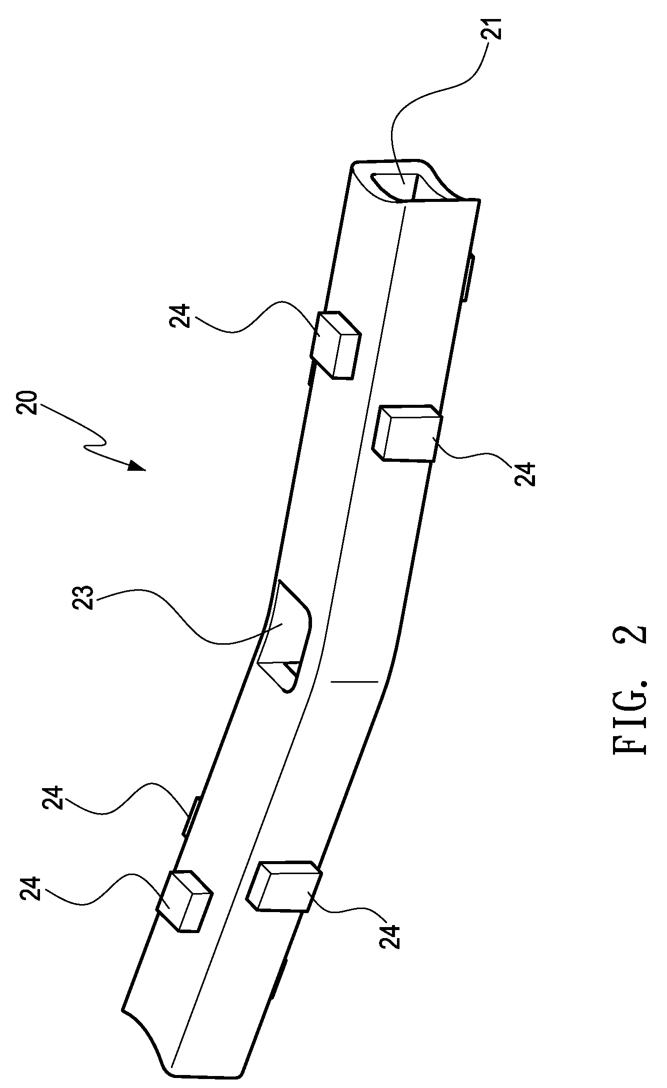
[0032]FIG. 6 is a cross-sectional view of the present invention. Referring to FIG. 6, in the finished product of the integral plastic faucet member fabricated in the above preferred embodiment of the present invention, besides that the first part may be molded with an inner water outlet in communication therewith above the middle part of the flow passage, the inner water outlet may also be molded below the middle part, two inner water outlets may be respectively molded above and below the middle part, such that the outer water outlet of the second part is formed at a position relative to the inner water outlet according to different water outlet requirements. Referring to FIG. 6, two inner water outlets 23a are molded above and below a middle part of a first part 20a respectively, and two corresponding outer water outlets 311a in communication with each other are molded at upper and lower sides of a wrapping part 31a of a second part 30a. After the finished product is fabricated, th...

third embodiment

[0033]In the second plastic injection molding f the process of the present invention, outer peripheral walls of the support leg parts may be directly molded with external threads for thread engagement (not shown). Similarly, inner peripheral walls or outer peripheral walls of the valve seat parts may also be directly injection molded with internal threads or external threads for thread engagement (not shown). FIG. 7 is a cross-sectional view of the present invention. Referring to FIG. 7, each support leg part 33b of a second part may be formed with an annular groove 333b on an outer peripheral wall thereof in plastic injection, and then, a copper member 34b with preformed external threads (not shown) on an outer peripheral wall thereof is engaged with and fixed to the annular groove 333b on each support leg part 33b through annular protrusions 341b protruding from an inner peripheral wall thereof, such that the outer peripheral wall of each support leg part 33b of the second part 30...


PUM

PropertyMeasurementUnit
timeaaaaaaaaaa
sizeaaaaaaaaaa
specific weightaaaaaaaaaa

Abstract

A process for fabricating an integral plastic faucet member and a finished product thereof are provided. The process mainly includes two injection steps. A first plastic injection is used to mold a first part at a middle connecting part of a faucet member. The first part is then placed into a mold for a second plastic injection so as to mold a second part at two sides of the faucet member. The second part is properly wrapped around and bonded to the first part. Meanwhile, desired holes are reserved to serve as water inlets, water outlets, and valve seats. Through such a two-injection process, the conventional complicated and time-consuming copper casting process is simplified, which improves the production efficiency and product quality, lows the cost and defective ratio. Meanwhile, the product weight is also reduced, which greatly reduces the transportation cost.

Description

BACKGROUND OF THE INVENTION[0001]1. Field of Invention[0002]The present invention relates to a faucet member, and more particularly to a process for fabricating an integral plastic faucet member and a finished product thereof.[0003]2. Related Art[0004]A conventional faucet component generally includes a faucet member, especially a faucet member with two water inlets. Such a faucet member is approximately H-shaped and has a left valve seat part, a right valve seat part, a connecting part between the valve seat parts, and support leg parts extending from bottom ends of the valve seat parts. The bottom end of each valve seat part has a water inlet. The water inlets may be respectively in communication with the valve seat parts above via an internal flow passage. A valve body may be mounted on each valve seat part and each of the valve bodies may be controlled by rotating a corresponding handle. In addition, the connecting part between the valve seat parts has an internal flow passage. ...

Claims


Application Information

Patent Timeline
Patent Type & Authority Applications(United States)
IPC IPC(8): B67D5/00B29C45/14
CPCB29C45/16F16K19/006B29L2031/769B29L2023/004Y10T137/6014Y10T137/87684Y10T137/9464
Inventor HOU, HSINE-CHANG
Owner GLOBE UNION INDAL
Features
  • Generate Ideas
  • Intellectual Property
  • Life Sciences
  • Materials
  • Tech Scout
  • Unparalleled Data Quality
  • Higher Quality Content
  • 60% Fewer Hallucinations
Learn More