Rotating electric machine and manufacturing method therefor

a technology of rotating electric machines and manufacturing methods, which is applied in the direction of mechanical energy handling, instruments, associations for rectification, etc., can solve the problems of deteriorating the shielding effect of noise, the adverse effect of rotation-position detection units, and the occurrence of variations in the performance of rotating electric machines

Active Publication Date: 2010-04-22
MITSUBISHI ELECTRIC CORP
View PDF9 Cites 23 Cited by
  • Summary
  • Abstract
  • Description
  • Claims
  • Application Information

AI Technical Summary

Benefits of technology

[0012]The present invention has been implemented in order to solve the foregoing problems in the conventional rotating electric machine; the objective thereo

Problems solved by technology

The change in the magnetic field appears as electromagnetic noise in other apparatuses and circuits, whereby an erroneous operation may be caused.
In particular, in a controller-integrated rotating electric machine, a control circuit unit provided with an inverter circuit including switching elements and a rotation-position detection unit that detects the rotation position of the rotor are arranged in the vicinity of each other; therefore, a change in the magnetic field caused by the rapid and abrupt change in an electric current reaches the region where the rotation-position detection unit is located, whereby the operation of the rotation-position detection unit may adversely be affected.
However, in the conventional rotating electric machine disclosed in Japanese Patent Laid-Open No. 2007-60734, when there occurs a deviation, i.e., a so-called positional deviation of the shielding member, formed of a magnetic material, from its original installation position, variations are produced in a magnetic field formed of the shield member and the magnetic portions, of the stator and the rotor, which configure the rotation-position detection unit; as a result, there has been anxieties of the occurrence of variations in th

Method used


Image

  • Rotating electric machine and manufacturing method therefor
  • Rotating electric machine and manufacturing method therefor
  • Rotating electric machine and manufacturing method therefor

Examples


embodiment 1

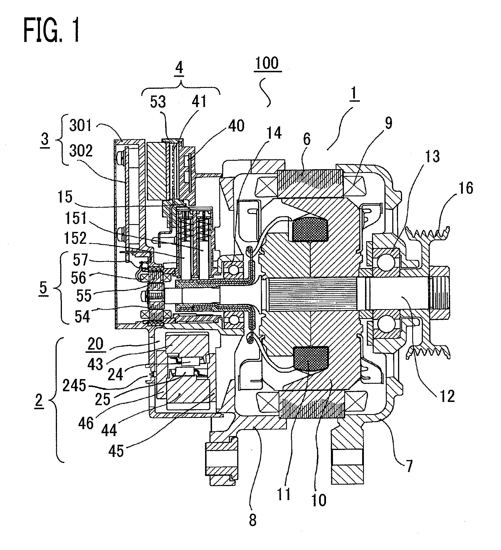
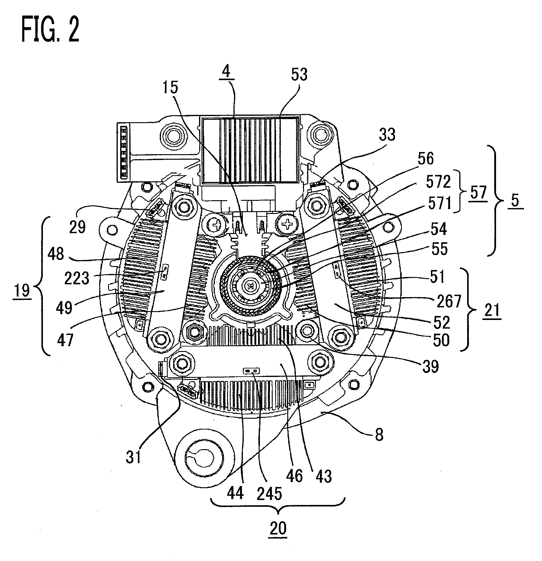
[0027]A rotating electric machine according to Embodiment 1 of the present invention will be explained with reference to the accompanying drawings. A rotating electric machine according to Embodiment 1 of the present invention is configured as a controller-integrated rotating electric machine and referred to as a controller-integrated rotating electric machine. FIG. 1 is a cross-sectional view of a rotating electric machine according to Embodiment 1 of the present invention; FIG. 2 is a plan view illustrating a power unit and a magnetic-field current control circuit unit mounted on a rear bracket of a rotating electric machine according to Embodiment 1 of the present invention; FIG. 3 is a circuit diagram of a rotating electric machine according to Embodiment 1 of the present invention.

[0028]In FIG. 1, a controller-integrated rotating electric machine 100 is configured with a rotating electric machine unit 1, a power unit 2, a control circuit unit 3, a magnetic-field current control...

embodiment 2

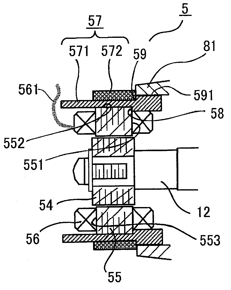
[0074]FIG. 7 is an enlarged schematic cross-sectional view of the rotation sensor unit in a rotating electric machine according to Embodiment 2 of the present invention. In FIG. 7, a rotation sensor unit 5 is provided with a sensor winding unit 56 having an excitation winding and a detection winding; the excitation winding and the detection winding of the sensor winding unit 56 are connected with a control circuit unit 3. In other words, the winding end portion is connected with the connection terminal of the control circuit unit 3.

[0075]In the rotating electric machine according to Embodiment 2, a notched portion 60 is provided in part of a non-magnetic unit 571 in a ring-shaped member 57, and the winding end portion 561 is pulled out through the notched portion 60 and connected with the control circuit unit 3. A magnetic unit 572 is formed along the axis direction in such a way as not to overlap the notched portion 60 of the non-magnetic unit 571 and to surround the whole circumfe...

embodiment 3

[0077]FIG. 8 is an enlarged schematic cross-sectional view of the rotation sensor unit in a rotating electric machine according to Embodiment 3 of the present invention. In FIG. 8, a winding end portion 561 of a sensor winding unit 56 in a rotation sensor unit 5 is preliminarily connected with a terminal member 62 molded in an insulative resin member 61. The resin member 61 is fixed inserted into a notched portion 60 in a non-magnetic unit 571 and is provided with a portion that protrudes from the notched portion 60 to the outside of the outer surface of the non-magnetic unit 571; the terminal member 62 is pulled out from the protrusion portion of the resin member 61 to the outside of the rotation sensor unit 5.

[0078]Because the resin member 61 is fixed inserted into the notched portion 60 in the non-magnetic unit 571, the position of the terminal member 62 is fixed with respect to the position of the ring-shaped member 57; therefore, it is prevented that variations in the position ...


PUM

PropertyMeasurementUnit
Lengthaaaaaaaaaa
Frequencyaaaaaaaaaa

Abstract

There is provided a rotating electric machine including a rotation sensor unit capable of demonstrating a shielding effect over a wide frequency bandwidth and a manufacturing method therefor. In the rotating electric machine, a power unit provided with a switching element that controls an electric current that flows in a stator winding and a magnetic-field current control circuit unit provided with a switching element that controls an electric current that flows in a rotor winding are arranged on a predetermined surface of one of a pair of brackets that pivotably support a rotor shaft, and the rotation sensor unit is disposed in the vicinity of the predetermined surface of the one bracket; The rotating electric machine is characterized in such a way that there is provided a ring-shaped member that is fixed on the outer surface of the rotation sensor unit, and the ring-shaped member is configured with a non-magnetic unit having an electric conductivity and a magnetic unit.

Description

BACKGROUND OF THE INVENTION[0001]1. Field of the Invention[0002]The present invention relates to a rotating electric machine such as a motor and a manufacturing method therefor, and more particularly to a rotating electric machine that can be installed in a relatively small space such as a place in a vehicle and to a manufacturing method therefor.[0003]2. Description of the Related Art[0004]To date, there has been well known a controller-integrated rotating electric machine in which a control circuit unit that controls a stator current or the like and a rotation-position detection unit that detects the rotation position of a rotor are integrated. The control of the output of such a rotating electric machine is performed by switching-controlling switching elements in an inverter circuit incorporated in the control circuit unit so as to control electric currents that flow in the windings of the rotating electric machine. In other words, the electric currents that flow in the windings ...

Claims


Application Information

Patent Timeline
IPC IPC(8): G01B7/30H02K15/00H02K23/66
CPCH02K11/0005Y10T29/49009H02K11/046H02K11/0031H02K11/225H02K11/0141H02K11/05
Inventor KIKUCHI, MASAOUTSUMI, YOSHINOBUISODA, HITOSHISHIRAKATA, YUJIFUJITA, MASAHIKO
Owner MITSUBISHI ELECTRIC CORP
Why Eureka
Try Eureka