Method and apparatus for while-drilling transient resistivity measurements

a technology of resistivity measurement and drill pipe, which is applied in the field of measuring tools, can solve the problems of reducing the sensitivity of the measured em field, the presence of imperfectly conductive drill pipe near the area, and the limited group of tools, and achieves the effect of high conductive material

Active Publication Date: 2010-04-22
BAKER HUGHES INC
View PDF15 Cites 61 Cited by
  • Summary
  • Abstract
  • Description
  • Claims
  • Application Information

AI Technical Summary

Benefits of technology

[0017]In one embodiment, an electromagnetic shield associated with the downhole assembly reduces an effect on the second transient electromagnetic signal of substantially direct coupling between the transmitter and the receiver. A magnetostatic shield associated with the downhole assembly reduces an effect on the second transient electromagnetic signal of currents induced in the downhole assembly by the first transient electromagnetic signal. The downhole assembly may include a bottomhole assembly conveyed on a drilling tubular. The magnetostatic shield may include a ferrite coating and/or a cut on the drilling tubular. The electromagnetic shield may comprise a highly conductive material. The apparatus may further include a processor configured to estimate from the second transient signal a distance t...

Problems solved by technology

This group of tools is naturally limited by, among other things, their applicability to only high resistivity formations and the power available down-hole.
One problem associated with the MWD environment is the presence of the metal (imperfectly conductive) drill pipe close to the area being measured.
This pipe produces a very strong response and significantly reduces the sensitivity of the measured EM field to the effects of formation resistivities and remote boundaries.
The sensitivity of such a tool to remote boundaries is low.
A disadvantage of both MPR and HDIL methods is that the primary source of induction from the transmitter is always present during the time frame in which the receivers are obtaining measurements from the formation, thereby distorting the intended signal.
Although the formation signal dominates at the late stage, it is also very small, and reliable measurement can be difficult.
Besides having limited resolution with respect to an oil/water boundary, such a system is very long (up to 10-...

Method used


Image

  • Method and apparatus for while-drilling transient resistivity measurements
  • Method and apparatus for while-drilling transient resistivity measurements
  • Method and apparatus for while-drilling transient resistivity measurements

Examples


Embodiment Construction

[0029]In the disclosure that follows, in the interest of clarity, not all features of actual implementations are described. It will of course be appreciated that in the development of any such actual implementation, as in any such project, numerous engineering and technical decisions must be made to achieve the developers' specific goals and subgoals (e.g., compliance with system and technical constraints), which will vary from one implementation to another. Moreover, attention will necessarily be paid to proper engineering and programming practices for the environment in question. It will be appreciated that such development efforts might be complex and time-consuming, outside the knowledge base of typical laymen, but would nevertheless be a routine undertaking for those of ordinary skill in the relevant fields.

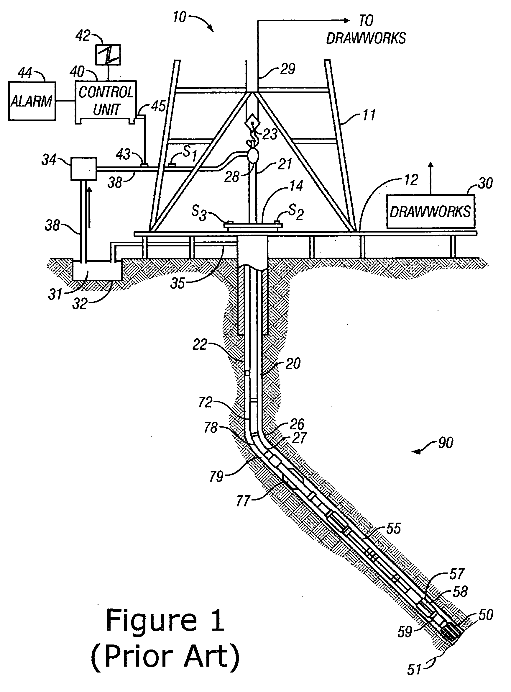
[0030]FIG. 1 shows a schematic diagram of a drilling system 10 with a drillstring 20 carrying a drilling assembly 90 (also referred to as the bottom hole assembly, or “BHA”)...


PUM


Abstract

Structure for deep MWD resistivity measurements suitable for both geo-steering and measurements ahead of the drill bit is disclosed. The structure is capable of extracting information about resistivity of formation in the presence of conductive drill. In one embodiment, ahead-of-bit sensing is achieved via transient electromagnetic measurements when current is switched off in the transmitter loop and the transient signal is measured in the receiver loops placed at some distances from the receiver. To reduce a parasitic effect of the currents in the drill three-coil bucking system with magnetic nonconductive shield in combination with a highly conductive copper shield are applied. Specifically, a short (less than 1 m) copper cover and short (less than 0.2 m) ferrite cover are placed in the vicinity of transmitting and receiving coils. A bucking operation followed by an inversion is performed on received signals to obtain data reflecting parameters of the surrounding subsurface formations.

Description

FIELD OF THE INVENTION[0001]The present invention relates generally to measurement tools used in hydrocarbon exploration and production, and more particularly to a measuring-while-drilling (MWD) tool for electromagnetic induction well loggingBACKGROUND OF THE INVENTION[0002]Electromagnetic induction resistivity instruments can be used to determine the electrical conductivity of earth formations surrounding a wellbore. An electromagnetic induction well logging instrument is described, for example, in U.S. Pat. No. 5,452,761 issued to Beard et al. The instrument described in the Beard '761 patent includes a transmitter coil and a plurality of receiver coils positioned at axially spaced apart locations along the instrument housing. An alternating current is passed through the transmitter coil. Voltages which are induced in the receiver coils as a result of alternating magnetic fields induced in the earth formations are then measured. The magnitude of certain phase components of the ind...

Claims


Application Information

Patent Timeline
IPC IPC(8): G01V3/28G01V3/30
CPCG01V3/28
Inventor ITSKOVICH, GREGORY B.REIDERMAN, ARCADY
Owner BAKER HUGHES INC
Why Eureka
Try Eureka