Driving circuit system and method of elevating slew rate of operational amplifier

a driving circuit and operational amplifier technology, applied in the direction of amplifiers with semiconductor devices only, differential amplifiers, amplifiers with semiconductor devices/discharge tubes, etc., can solve the problems of reducing the stability of the operational amplifier, reducing the response speed, and not ideal voltage output signals, etc., to prevent the negative influence of the charge sharing structure, accelerate the response time, and enhance the effect of bias

Active Publication Date: 2010-04-22
RAYDIUM SEMICON
View PDF3 Cites 12 Cited by
  • Summary
  • Abstract
  • Description
  • Claims
  • Application Information

AI Technical Summary

Benefits of technology

[0028]The edge trigger mentioned in the invention can be a positive edge trigger and / or a negative edge trigger. In an embodiment, the invention can respectively sense the rising edge (positive edge) and the falling edge (negative edge), at which the control signal begins to change, and generate the bias enhancing signal. It may respectively generate the additive current for cooperating with the bias current to drive the input stage of the operational amplifier, such that the slew rate of the operational amplifier is elevated at these two time points (rising edge and falling edge). Accordingly, it may respectively prevent the negative influence from the charge sharing structure and accelerate the response time of the operational amplifier served as the output buffer.
[0029]The driving circuit system and the method of elevating a slew rate of an operational amplifier of the invention utilize a simple current switching circuit to cooperate with the existing control signal for elevating the slew rate of the operational amplifier at particular time point. Compared with prior art, the driving circuit system of the invention may only utilize simple circuit structure and signal judgment to accelerate the response time of the operational amplifier under low steady current consumption, and to reduce the problem caused by the charge sharing structure at the same time. It can be implemented in a source driver circuit of a large-sized and fast-responding display device.
[0030]The advantage and spirit of the invention may be understood by the following recitations together with the appended drawings.

Problems solved by technology

With the LCD displaying technology developing, the LCD monitor is heading to have a higher display resolution, a larger size and a rapider response time, therefore, there are more challenges in design the driving circuit.
In general, when the voltage output signal of the output buffer is switched, the changing of the voltage output signal is not ideal but has a certain delay.
That is to say, while the source driver circuit is generating the voltage output signal, the settling time Ts is needs for the LCD monitor to complete its function, such that the response speed is limited.
However, it reduces the stability of the operational amplifier.
However, the extra differential amplifier circuit may complex the driving circuit, and further to enlarge the die size of the driving circuit and the static current consumption.
On the other hand, in order to drive a great deal of pixel loads, the present source driver circuit must have a lots of the driving circuit (such as said driving circuit system 1) for corresponding the pixel loads, and it results in a heavy consumption of electricity.
However, the driving circuit system with charge sharing structure would generate an output voltage noise (as the noise N shown in FIG. 5) at the negative edge of the control signal C (usually the STB signal in practical usage).
The noise decreases the stability of the driving circuit system.

Method used


Image

  • Driving circuit system and method of elevating slew rate of operational amplifier
  • Driving circuit system and method of elevating slew rate of operational amplifier
  • Driving circuit system and method of elevating slew rate of operational amplifier

Examples


first embodiment

[0046]Please refer to FIG. 6. FIG. 6 is a schematic diagram illustrating a driving circuit system 3 according to the invention. As shown in FIG. 6, the driving circuit system 3 includes an operational amplifier 30, an output switch 31, a judging module 32 and a bias enhancing module 34.

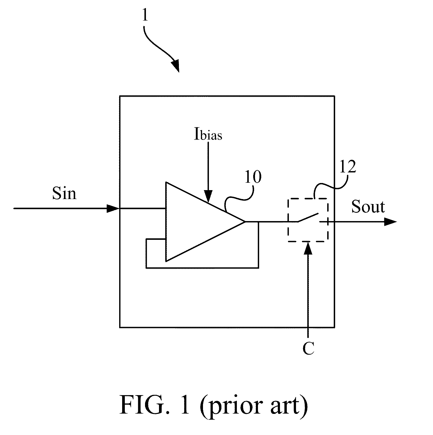
[0047]In the embodiment, the operational amplifier 30 has an electronic feedback loop connected between the output terminal and one of the input terminals of the operational amplifier 30. In theory of a latch structure, the operational amplifier 30 with the electronic feedback loop may act like an output buffer. The output terminal of the operational amplifier 30 is further connected to the output switch 31. The output switch 31, controlled by a control signal C, can cooperate with the operational amplifier 30 and can be switched between the action of registering the input signal Sin and the action of generating output signal Sout performed by the output buffer. The control signal C here can be an STB...

third embodiment

[0066]Please refer to FIG. 12. FIG. 12 is a flowchart illustrating a method of elevating a slew rate of an operational amplifier according to the invention. The method includes steps as follows. Firstly, step M01 is performed to generate a bias enhancing signal according to an edge trigger of a control signal. The control signal C can be a STB signal or an equivalent pulse signal. The control signal C is used for switching the actions performed by the output buffer between registering the input signal Sin and generating output signal Sout. The edge trigger mentioned in the invention can be a positive edge trigger and / or a negative edge trigger. In practical application, it may respectively prevent the negative influence from the charge sharing structure and accelerate the response time of the operational amplifier served as the output buffer.

[0067]Afterward, step M02 is performed to receive the bias enhancing signal and generate an additive current. In an embodiment, the bias enhanc...


PUM


Abstract

The invention discloses a driving circuit system and a method of elevating a slew rate of an operational amplifier. The driving circuit system comprises an operational amplifier, a judging module and a bias enhancing module. The operational amplifier has an input stage driven by a bias current. The bias enhancing module is electrically connected to the judging module and the input stage of the operational amplifier respectively. The judging module is used to generate a bias enhancing signal according to an edge-trigger of a control signal. When the bias enhancing module receives the bias enhancing signal, the bias enhancing module provides an additional current, which cooperates with the bias current, for driving the input stage of the operational amplifier, so as to elevating a slew rate of the operational amplifier.

Description

BACKGROUND OF THE INVENTION[0001]1. Field of the Invention[0002]The invention relates to a driving circuit system and a method of elevating a slew rate and. More particularly, the invention relates to a driving circuit system having an operational amplifier (op-amp) with a high slew rate and a method of elevating a slew rate of an operational amplifier.[0003]2. Description of the Prior Art[0004]The operational amplifier structure has a lot of application in modern electronic appliance. For example, the amplifying circuit used in signal processing, the driving circuit used in driving a capacitive load and the signal converting circuit used in converting signals between analog and digital are both practical implements with the operational amplifier structure. Especially, the liquid crystal display (LCD) monitor must drive a great deal of pixel capacitors to compose the displaying image, so that the operational amplifier is usually adopted in a driving circuit.[0005]With the LCD displa...

Claims


Application Information

Patent Timeline
Patent Type & Authority Applications(United States)
IPC IPC(8): H03F3/16
CPCH03F3/3022H03F3/45219H03F2203/45248H03F2203/45206H03F3/45475
Inventor LIANG, YANN HSIUNGTSO, KO YANGCHAO, CHIN CHIEH
Owner RAYDIUM SEMICON
Why Eureka
Try Eureka