Methods and apparatus for monitoring particles flowing in a stack

a technology of monitoring and particles, applied in chemical methods analysis, instruments, liquid/fluent solid measurements, etc., can solve the problems of difficult to audit the technique with a surrogate, small measurement volume, and drift of calibration, so as to improve the overall performance, enhance the resolution and representative performance of electrodynamic measurement, and improve the overall performance.

Active Publication Date: 2010-04-29
POLLUTION CONTROL & MEASUREMENT EURO
View PDF4 Cites 14 Cited by
  • Summary
  • Abstract
  • Description
  • Claims
  • Application Information

AI Technical Summary

Benefits of technology

[0011]The apparatus thus combines electrodynamic and light scatter technology in the same instrument to obtain better overall performance than the techniques provide when used separately. The robust, high resolution and representative performance of the electrodynamic measurement is enhanced by the more stable accuracy and auditability characteristics of light scatter.
[0012]The electrodynamic signal is referenced periodically against the more stable scattered-light signal, reducing the need for costly calibrations of the electrical-interaction monitor with a gravimetric sample. The apparatus may thus be used in applications where electrodynamic instruments cannot normally be used, for example processes from which particulate is controlled with Electrostatic Precipitator abatement equipment (common in the power industry) and varying velocity applications (in both of those applications, the charge on the flowing particles can change with time, making prior-art electrodynamic instruments not sufficiently accurate).
[0013]The instrument need only make light-scatter measurements intermittently, which means that its optical components need only be exposed to dust for short durations, hence reducing the need for costly air purges and window cleaning, and increasing the reliability of the instrument.
[0014]Also, in electrodynamic mode, the instrument has a much larger measurement volume than a light-scatter detector, thus providing a more representative measurement of stack emissions, as well as more robust operation and higher resolution.

Problems solved by technology

Their major shortcomings are that calibration can drift over time, particularly if the average charge on the flowing particles changes, and that it is difficult to audit the technique with a surrogate (we know of no good surrogate for dust which accurately simulates dust interaction with the rod).
Their major shortcomings are that the measurement volume is relatively small and that it is difficult to keep optical surfaces clean (which can cause drift in the measurement) even using sophisticated air purges.

Method used


Image

  • Methods and apparatus for monitoring particles flowing in a stack
  • Methods and apparatus for monitoring particles flowing in a stack
  • Methods and apparatus for monitoring particles flowing in a stack

Examples


Embodiment Construction

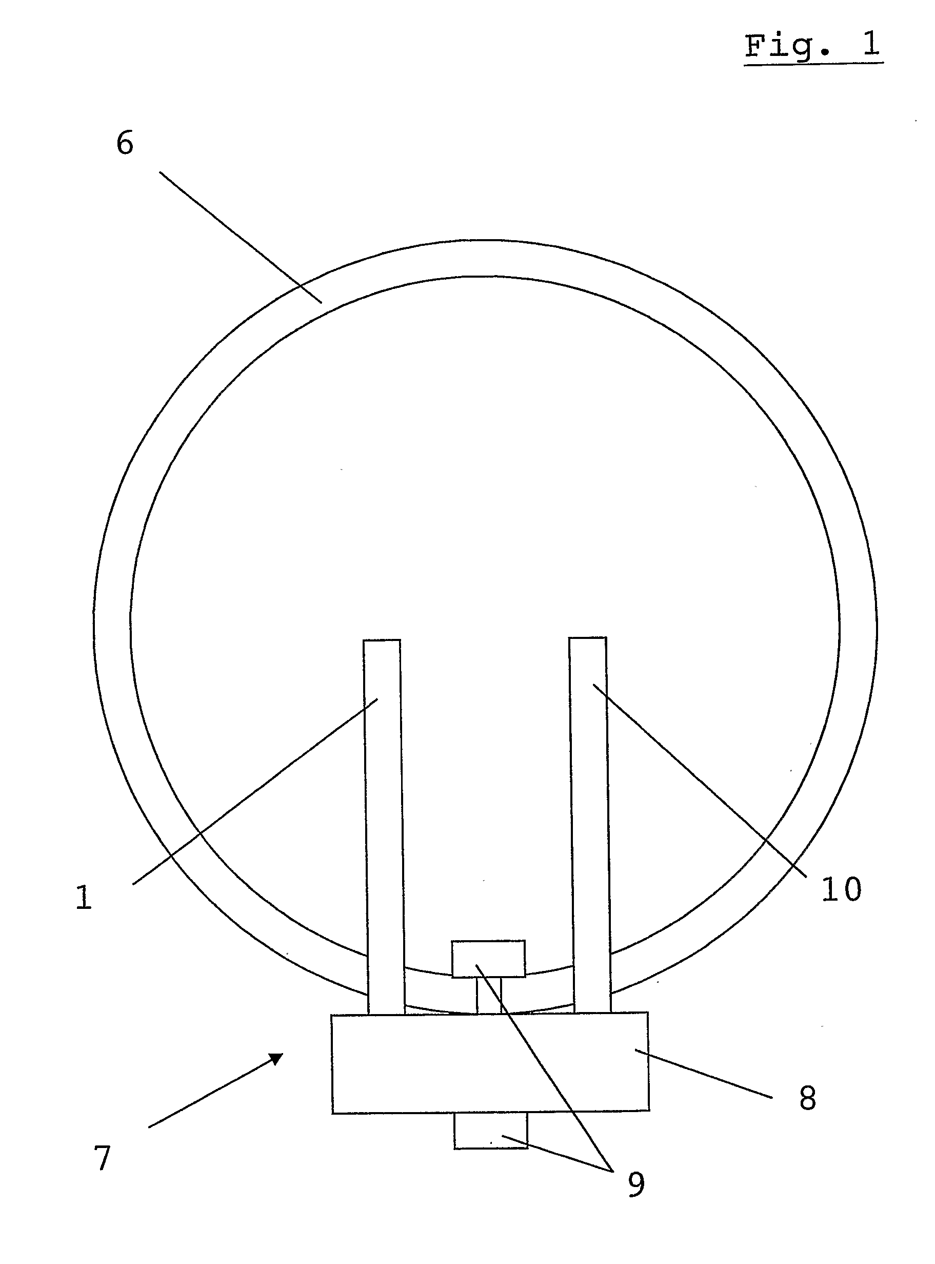
[0057]In FIG. 1, an example particle monitoring apparatus 7 according to an embodiment of the invention is shown mounted in the wall of a stack 6. Apparatus body 8 is mounted outside the stack 6 by mounting means 9. Two probes 1, 10 project from the body 8 through the wall into the interior of stack 6.

[0058]The first probe 1 is a rod for measuring electrical signals arising from interactions between particles flowing in stack 6. The second probe 10 is for measuring light scattering from the particles.

[0059]The apparatus can operate in 3 modes:

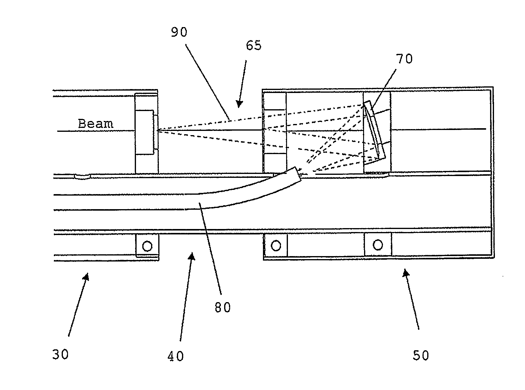
[0060](1) Electrodynamic running mode: this is the most common mode of operation in which the electrodynamic signal is measured and the dust concentration is derived by multiplying this signal by a predetermined calibration factor. In this mode the light scatter detector is not operational and all optics are protected from the process gas and dust.

[0061](2) Referencing mode: in which the electrodynamic signal and light scatter signal are period...


PUM

PropertyMeasurementUnit
lengthaaaaaaaaaa
frequencyaaaaaaaaaa
frequencyaaaaaaaaaa

Abstract

An apparatus (7) for monitoring particles flowing in a stack (6), comprises: an electrical-interaction monitor (1) operable to provide a signal (300) resulting from electrical interaction of the particles with the monitor (1). a scattered-light monitor (10) operable to provide a signal (310) resulting from detection of light scattered from the particles, and a controller (320) arranged to alter the calibration of the electrical-interaction monitor 1 in response to changes in the relative magnitude of the electrical-interaction (signal 300) and the scattered-light signal (310).

Description

FIELD OF THE INVENTION[0001]This invention relates to monitoring particles flowing in a stack. More particularly, although not exclusively, the present invention relates to calibration of apparatus for monitoring such particle flows. Even more particularly, although not exclusively, the present invention relates to independent auditing of the calibration of such apparatus.BACKGROUND ART[0002]Particulates emitted from industrial stacks are monitored for a number of reasons. Several countries impose regulatory restrictions on emissions, and monitoring is necessary to ensure compliance. Increasingly, companies have their own internal environmental programs and monitor emissions to provide data for those, and for their internal quality control procedures. Companies also monitor emissions in order to improve their own processes, for example by improving powder production, reducing product loss from process-particle collection devices and reducing running costs of fabric filters (by exten...

Claims


Application Information

Patent Timeline
Patent Type & Authority Applications(United States)
IPC IPC(8): G01N27/00G01N21/00
CPCG01N15/0205G01N2015/0693G01N15/0656G01F1/64G01N15/06G01N21/53
Inventor RIGBY, MICHAELAVERDIECK, WILLIAM JOHN
Owner POLLUTION CONTROL & MEASUREMENT EURO
Why Eureka
Try Eureka