Positive crankcase ventilation system, cylinder head used for positive crankcase ventilation system, internal combustion engine including positive crankcase ventilation system, and positive crankcase ventilation method

a technology of positive crankcase and ventilation system, which is applied in the direction of cylinders, combustion engines, machines/engines, etc., can solve the problems of increasing the amount of oil consumption, reducing the output of the engine, and reducing the level of so as to reduce the manufacturing cost, improve the level of the blow-by gas handling performance of the positive crankcase ventilation system, and simplify the manufacturing process

Inactive Publication Date: 2010-04-29
TOYOTA JIDOSHA KK
View PDF22 Cites 55 Cited by
  • Summary
  • Abstract
  • Description
  • Claims
  • Application Information

AI Technical Summary

Benefits of technology

[0028]The first breather chamber may be formed by a breather case attached to a head cover provided on the cylinder head; and the connection portion may be a gap between a cutout portion formed in an upper end portion of the partition wall, and a lower surface of the breather case.
[0029]In this case, the partition wall may include a protruding portion that protrudes toward the inner space of the cylinder head; an inside of the protruding portion may function as the blow-by gas collection passage; an upper end of the protruding portion may be disposed at a position lower than an upper end portion of the cylinder head by forming the cutout portion; and the connection portion may be a gap between the upper end of the protruding portion and the lower surface of the breather case when the lower surface of the breather case contacts an upper end surface of the cylinder head.
[0030]In the configuration, the connection portion is formed only by forming the cutout portion in the cylinder head. Therefore, when the cylinder head is manufactured, a manufacturing process (for example, a casting process) is simplified. This reduces manufacturing cost. Also, in the system where the connection portion is formed between the upper end of the protruding portion and the lower surface of the breather case, the new air is introduced into a relatively large range in the circumferential direction of the blow-by gas collection passage. Therefore, the blow-by gas is diluted by mixing the new air into the blow-by gas in a relatively large area in the blow-by gas collection passage. Accordingly, the entire blow-by gas to be introduced into the first breather chamber is uniformly diluted.
[0031]The following configurations are made taking into account the operating state of the internal combustion engine in which the amount of generated blow-by gas increases. In the first breather chamber, oil contained in the blow-by gas introduced into the first breather chamber through the blow-by gas collection passage may be separated from the blow-by gas. Also, a second breather chamber connected to the inner space of the cylinder head with the intake system for the internal combustion engine may be provided in the upper portion of the cylinder. In the second breather chamber, the oil may be separated from the blow-by gas.
[0032]Thus, when the amount of generated blow-by

Problems solved by technology

In most cases, the blow-by gas collection passage “b” is disposed at a position under the influence of the temperature of outside air, due to limitations of space where the blow-by gas collection passage is disposed.
This may make it impossible to discharge the oil from the oil separator “g” toward the oil pan “k”.
This may decrease the output from the engine, and increase the amount of oil consumption.
Also, in the system where the oil return passage “i” is used also as the air introduction passage, it may be diffi

Method used


Image

  • Positive crankcase ventilation system, cylinder head used for positive crankcase ventilation system, internal combustion engine including positive crankcase ventilation system, and positive crankcase ventilation method
  • Positive crankcase ventilation system, cylinder head used for positive crankcase ventilation system, internal combustion engine including positive crankcase ventilation system, and positive crankcase ventilation method
  • Positive crankcase ventilation system, cylinder head used for positive crankcase ventilation system, internal combustion engine including positive crankcase ventilation system, and positive crankcase ventilation method

Examples


modified example

[0108]Next, modified examples of the invention will be described. In each of the modified examples described below, the shape of the cutout portion 97b, which is formed by cutting out a portion of the protruding portion 97a to form the connection portion 98, is different from the shape of the cutout portion 97b in the above-described embodiment. The other portions of the configuration are the same as those in the above-described embodiment. Therefore, only the shape of the cutout portion 97b will be described.

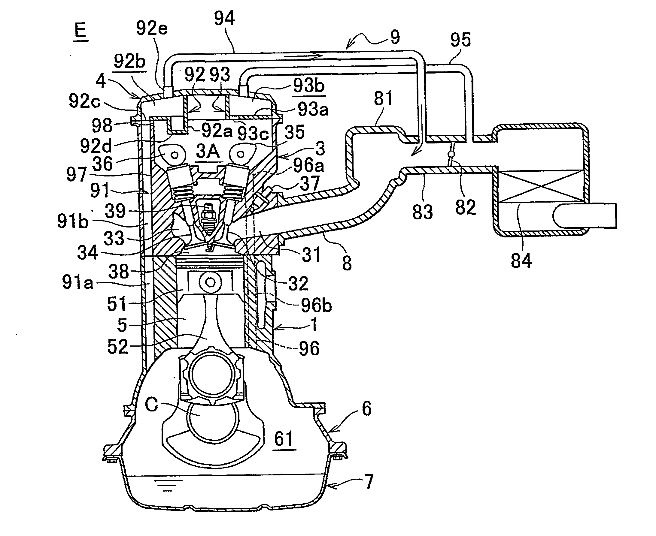
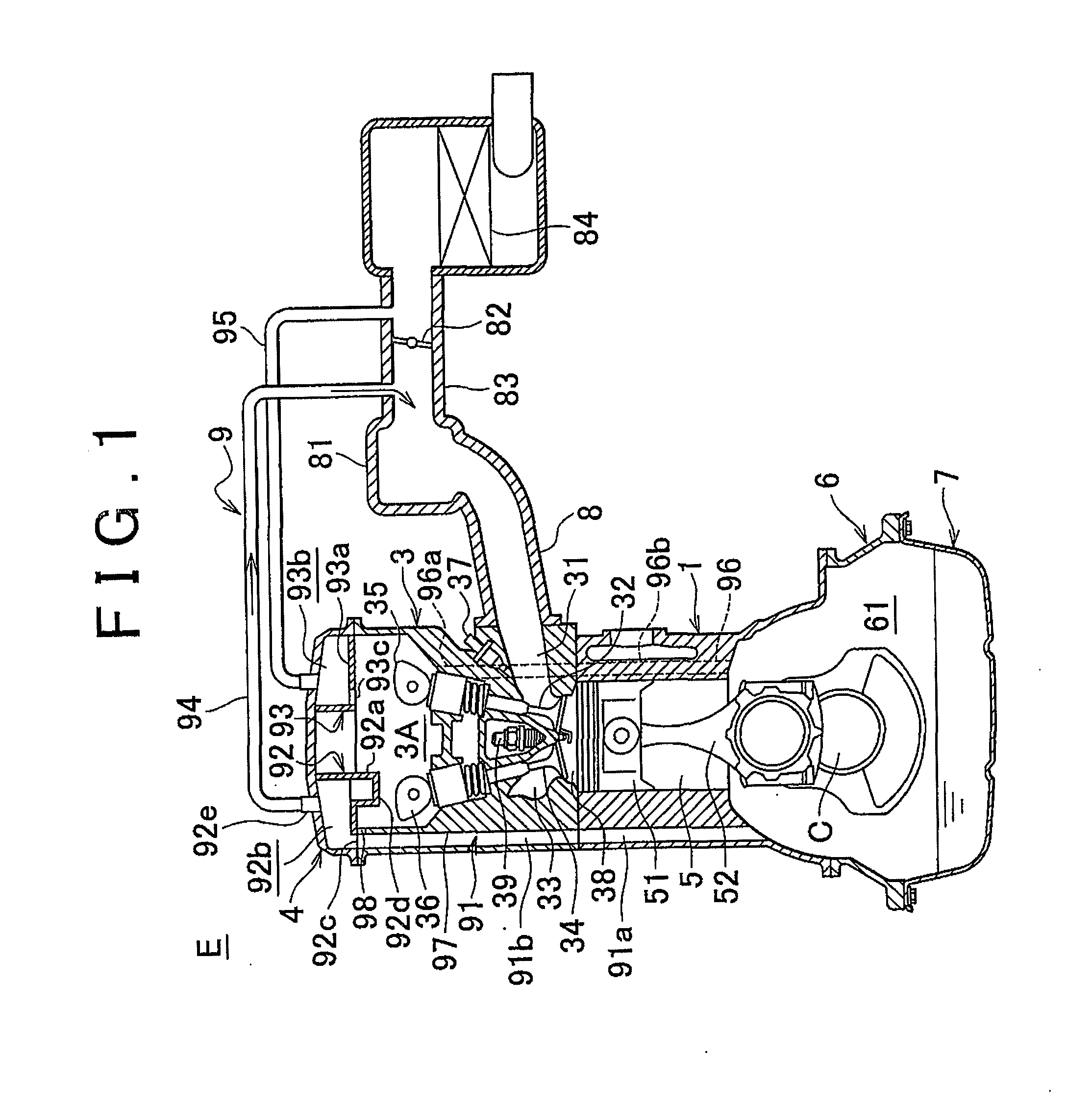
[0109]FIGS. 8A and 8B show a first modified example. FIGS. 9A and 9B show a second modified example. Each of FIG. 8A and FIG. 9A is a perspective view showing a portion of the cylinder head 3, in which the blow-by gas collection passage 91 (91b) is formed. Each of FIG. 8B and FIG. 9B is a plane view showing the same portion of the cylinder head 3, and the camshaft 36.

[0110]In each of the modified examples, the cutout portion 97b is formed so that the oil splashed from a cam nos...


PUM


Abstract

A blow-by gas collection passage (91) extends in a cylinder block (1) and a cylinder head (3). A crank chamber (61) is connected to an oil separator (92) through the blow-by gas collection passage (91). A cutout portion is formed in an upper end portion of a wall portion (97) of the blow-by gas collection passage (91), and the oil separator (92) contacts an upper surface of the cylinder head (3) to form a connection portion (98) through which the blow-by gas collection passage (91) is connected to a cam chamber (3A). Thus, new air in the cam chamber (3A) flows into the blow-by gas collection passage (91) at an inlet portion of the oil separator (92) through the connection portion (98) to dilute the blow-by gas.

Description

BACKGROUND OF THE INVENTION[0001]1. Field of the Invention[0002]The invention relates to a positive crankcase ventilation system (hereinafter, referred to as “PCV system”) that delivers blow-by gas in an internal combustion engine provided in a vehicle or the like to an intake system. The invention also relates to a cylinder head used for the PCV system, an internal combustion engine including the PCV system, and a positive crankcase ventilation method. Particularly, the invention relates to improvement of a PCV system that includes a blow-by gas collection passage through which an inside of a crankcase is connected to an inside of a breather chamber, and improvement of a positive crankcase ventilation method.[0003]2. Description of the Related Art[0004]In related art, an internal combustion engine for a vehicle includes a PCV system that introduces blow-by gas, which has been blown into a crankcase through a gap between a cylinder and a piston, into an intake system. That is, using...

Claims


Application Information

Patent Timeline
IPC IPC(8): F01M13/00F02B25/06
CPCF01M13/028F01M13/022
Inventor HIRANO, SATOSHIIMAI, YASUAKI
Owner TOYOTA JIDOSHA KK
Why Eureka
Try Eureka