Phase Estimation From Rotating Sensors To Get a Toolface

a technology of phase estimation and rotating sensors, applied in the field of accelerators, can solve the problems of compromising the accuracy of position measurements, not being able to measure the earth's magnetic field and being particularly problematic in the presence of ferrous or ferromagnetic materials

Inactive Publication Date: 2010-04-29
BAKER HUGHES INC
View PDF3 Cites 105 Cited by
  • Summary
  • Abstract
  • Description
  • Claims
  • Application Information

AI Technical Summary

Problems solved by technology

The varying magnetic azimuth compromises the accuracy of the position measurements when magnetometers are used.
Additionally, it is not feasible to measure the earth's magnetic field in the presence of ferrous or ferromagnetic materials, such as casing and drill pipe.
The presence of ferrous or ferromagne

Method used


Image

  • Phase Estimation From Rotating Sensors To Get a Toolface
  • Phase Estimation From Rotating Sensors To Get a Toolface
  • Phase Estimation From Rotating Sensors To Get a Toolface

Examples


Embodiment Construction

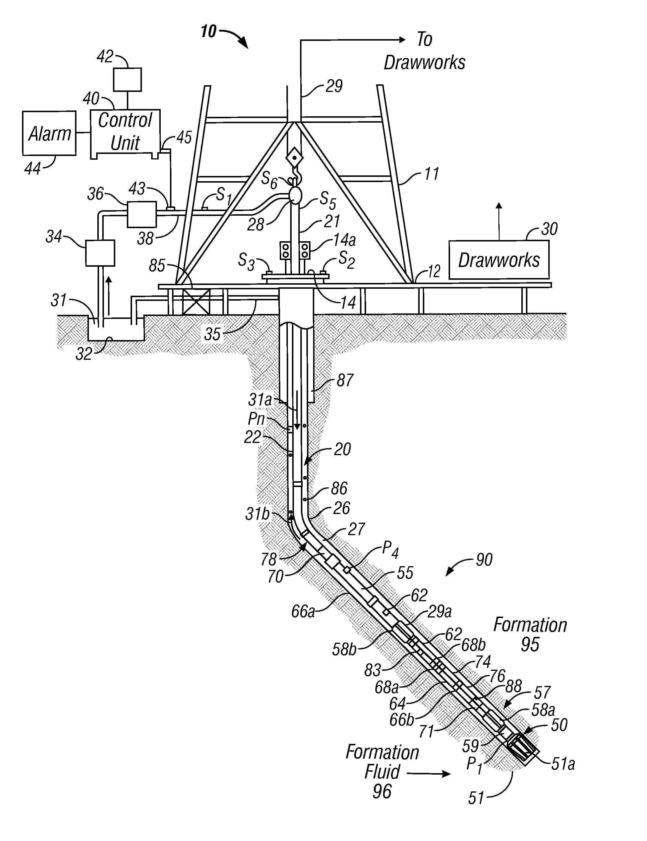
[0016]FIG. 1 (prior art) shows a schematic diagram of a drilling system 10 having a bottom hole assembly (BHA) or drilling assembly 90 that includes gyroscope(s) according to the present disclosure. The BHA 90 is conveyed in a borehole 26. The drilling system 10 includes a conventional derrick 11 erected on a floor 12 which supports a rotary table 14 that is rotated by a prime mover such as an electric motor (not shown) at a desired rotational speed. The drill string 20 includes a tubing (drill pipe or coiled-tubing) 22 extending downward from the surface into the borehole 26. A drill bit 50, attached to the drill string 20 end, disintegrates the geological formations when it is rotated to drill the borehole 26. The drill string 20 is coupled to a drawworks 30 via a kelly joint 21, swivel 28 and line 29 through a pulley (not shown). Drawworks 30 is operated to control the weight on bit (“WOB”), which is an important parameter that affects the rate of penetration (“ROP”). A tubing in...


PUM


Abstract

Measurements made by a rotating sensor on a bottomhole assembly are used to determine the toolface angle of the BHA. The method includes using a phase locked loop (PLL) to determine a phase difference between the sensor output and a reference signal.

Description

FIELD OF THE DISCLOSURE[0001]This disclosure relates generally to bottom hole assemblies for drilling oilfield wellbores and more particularly to the use of accelerometers to determine wellbore and drilling tool direction during the drilling of the wellbores.BACKGROUND OF THE DISCLOSURE[0002]To obtain hydrocarbons such as oil and gas, wellbores (also referred to as the boreholes) are drilled by rotating a drill bit attached at the end of a drilling assembly generally referred to as the “bottom hole assembly” (BHA) or the “drilling assembly.” A large portion of the current drilling activity involves drilling highly deviated and substantially horizontal wellbores to increase the hydrocarbon production and / or to withdraw additional hydrocarbons from the earth's formations. The wellbore path of such wells is carefully planned prior to drilling such wellbores utilizing seismic maps of the earth's subsurface and well data from previously drilled wellbores in the associated oil fields. Due...

Claims


Application Information

Patent Timeline
IPC IPC(8): E21B7/12E02B17/08G06F17/30
CPCE21B47/024E21B7/068
Inventor WASSERMANN, INGOLFZHANG, FANGKELCH, THOMASBONG, LEVIN L.KRUEGER, SVEN
Owner BAKER HUGHES INC
Why Eureka
Try Eureka