Source driver structure for display and output control circuit thereof

Active Publication Date: 2010-04-29
CHUNGHWA PICTURE TUBES LTD
View PDF7 Cites 19 Cited by
  • Summary
  • Abstract
  • Description
  • Claims
  • Application Information

AI Technical Summary

Benefits of technology

[0012]The object of present invention is to provide a source driver structure to solve the power-on noise

Problems solved by technology

The manufacture of source driver circuit requires the analog-to-digital technology whose design is much complicated.
On the other hand, the gate driver circuit decides the position to display the image and inform each row of pixel to implement the data input process including the step of indicating the switch state (ON/OFF) of the transistor, deciding the twisted angle and speed of the liquid crystal cell, thus it's manufacturing process is more difficult.
The output signal is unstable random data at this time causing the LCD displayer to display random pattern when the power-on, which is the so called power-on noise issue in the LCD displayer.
However, a large number of NAND gate are require

Method used


Image

  • Source driver structure for display and output control circuit thereof
  • Source driver structure for display and output control circuit thereof
  • Source driver structure for display and output control circuit thereof

Examples


Embodiment Construction

[0020]The invention will now be described in greater detail with preferred embodiments of the invention and illustrations attached. Nevertheless, it should be recognized that the preferred embodiments of the invention is only for illustrating. Besides the preferred embodiment mentioned here, present invention can be practiced in a wide range of other embodiments besides those explicitly described, and the scope of the present invention is expressly not limited expect as specified in the accompanying Claims.

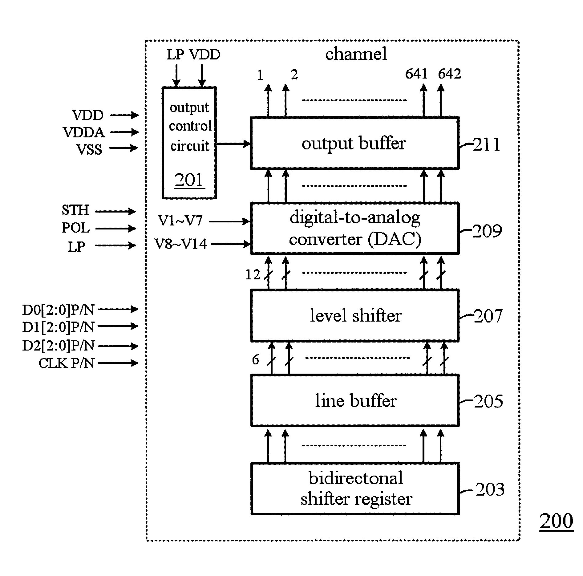
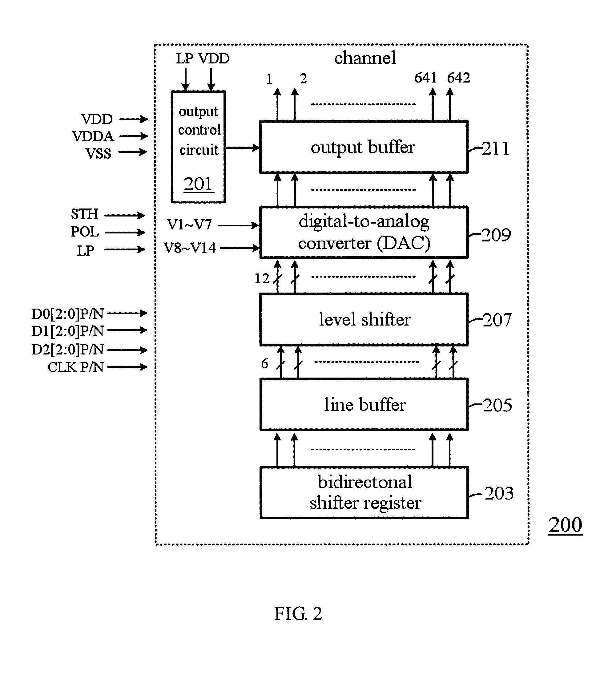
[0021]Referring now to FIG. 2, a circuit diagram of source driver in the preferred embodiment of present invention is illustrated. As shown in the drawing, the source driver circuit of the present invention includes an output control circuit 201, a bidirectional shift register 203, a line buffer 205, level shifter 207, a digital-to-analog converter (DAC) 209, and a output buffer 211. First, the bidirectional shift register 203 in the embodiment inputs and registers a data signal i...


PUM


Abstract

The present invention discloses an source driver circuit scheme for displayer, which comprises a shifter register to register data signal, a line buffer coupled with said shifter register to latch the data signal, a level shifter coupled with line buffer to level output electrical potential, a digital-to-analog converter (DAC) to convert digital signal to analog signal, an output buffer coupled with said digital-to-analog converter (DAC) to output converted signal, and an output control circuit coupled with output buffer. Said output control circuit comprises a D flip-flop and CMOS switching element to output a LP_out signal and control the data signal output of the source driver IC to avoid the power-on noise of the displayer.

Description

FIELD OF THE INVENTION[0001]The present invention generally pertains to an output control circuit for the source driver in panel displayer, more particularly, relates to an output control circuit to eliminate the power-on noise of panel displayer.DESCRIPTION OF THE PRIOR ART[0002]Recently, due to the remarkable advancing and prosperous development in image display technology, most of the traditional cathode ray tube (CRT) displayer has been replaced by the so called panel displayer. The panel displayer has the advantages of small size, thin thickness, light weight, low power consumption, and low radiation in comparison with the bulky CRT displayer and thereby becomes the dominant technology of the image displayer in current generation. Nowadays, the thin-film transistor liquid crystal displayer (TFT-LCD) is the most common flat panel displayer in the market, the other flat panel displayers such as the one utilizing light emitting diode (LED) or plasma technology become more and more...

Claims


Application Information

Patent Timeline
IPC IPC(8): H04N5/04
CPCH04N5/70G09G3/3688
Inventor LI, MING-XIANHUANG, CHIAO-LIN
Owner CHUNGHWA PICTURE TUBES LTD
Why Eureka
Try Eureka