Centrifugal precipitating method and light emitting diode and apparatus using the same

a technology of light emitting diodes and precipitation methods, applied in the direction of lighting and heating apparatus, light fastenings, lighting support devices, etc., can solve the problems of not all types of glues can have a specific gravity, fluorescent powder cannot be precipitated successfully on the bottom of the bowl-shaped recess, and the time cost of manufacturing led is increased, so as to achieve efficient precipitation of fluorescent particles and improve the conformity rate and quality of led

Inactive Publication Date: 2010-04-29
WELLYPOWER OPTRONICS CORP
View PDF3 Cites 14 Cited by
  • Summary
  • Abstract
  • Description
  • Claims
  • Application Information

AI Technical Summary

Benefits of technology

[0010]The invention is directed to a centrifugal precipitating method and a light emitting diode (LED) and an apparatus using the same. A lighting structure is rotated so as to provide a centrifugal force thereto, and the fluorescent particles of the colloid are moved toward a bottom surface of the recess, whereby achieve the effect of efficiently precipitating the fluorescent particles. In an embodiment, the particle diameter of the fluorescent particles is preferably but non-limitedly less than 30 μm. According to the disclosure, the surface of the colloid in the lighting structure becomes even while the bubbles that are formed by the air in the colloid are also discharged. Thus, the light emitting effect, conformity rate and quality of the LED are correspondingly increased.

Problems solved by technology

However, not all types of glue can have a specific gravity which is significantly different from that of the fluorescent powder when being heated.
As such, it is possible that the fluorescent powder can not be precipitated on the bottom of the bowl-shaped recess successfully.
Thus, the time cost for manufacturing LED is increased, and the overall productivity of LED is decreased accordingly.
Thus, under the requirement of high efficiency, it is an imminent issue for the manufacturers to provide a method and apparatus capable of precipitating the fluorescent powder on the bottom of the recess and whereby increasing both of the light emitting effect and quality of LED.

Method used


Image

  • Centrifugal precipitating method and light emitting diode and apparatus using the same
  • Centrifugal precipitating method and light emitting diode and apparatus using the same
  • Centrifugal precipitating method and light emitting diode and apparatus using the same

Examples


first embodiment

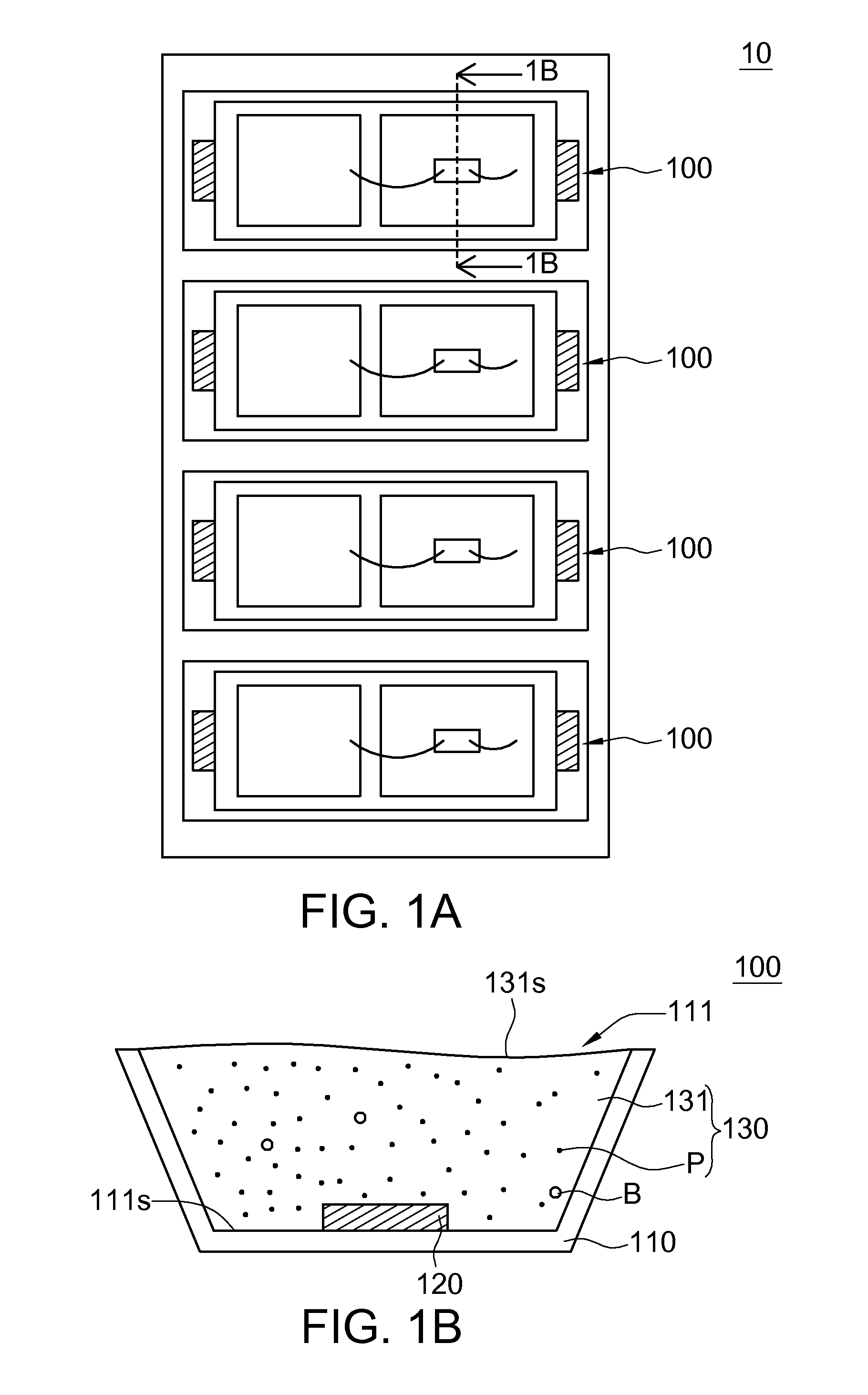
[0029]The present embodiment of the invention is exemplified by performing the centrifugal precipitating method on the lighting structure 10 in FIG. 1A for illustration. FIG. 1A is a schematic diagram showing an example of a lighting structure. The lighting structure 10 includes a number of pre-precipitated LEDs 100 which are not precipitated and divided yet.

[0030]FIG. 1B is a cross-sectional view showing a pre-precipitated LED along the cross-sectional line 1B-1B of FIG. 1A. The pre-precipitated LED 100 includes a frame 110, a chip 120 and a colloid 130. The frame 110 has a recess 111 of bowl-shaped for example. The chip 120 is disposed on a bottom surface 111s of the recess 111 for emitting a blue light for example. The colloid 130 includes two types of glue 131 (such as a mixture of A-type of glue and B-type of glue) and several yellowish fluorescent particles P. The glue 131 is filled in the recess 111 and covers the chip 120. The fluorescent particles P are distributed in the g...

second embodiment

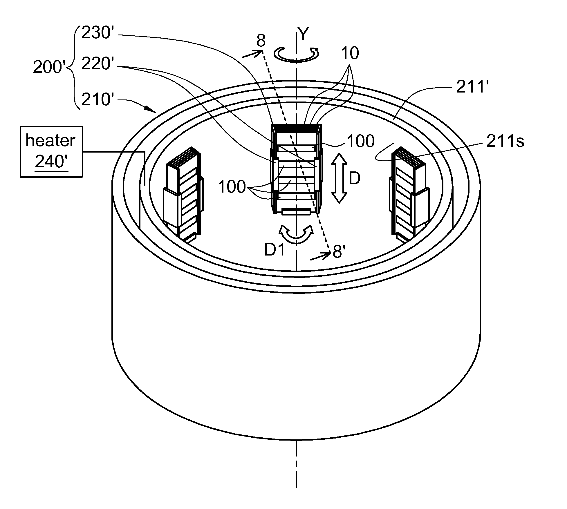
[0043]This embodiment differs with the first embodiment in the design of the cartridge, the heater and the fixing mechanism of a centrifugal precipitating apparatus. Similar or identical components in the embodiment are labeled with similar or identical reference numbers and repetitive descriptions are not repeated here. Besides, the present embodiment of the invention is again taken the pre-precipitated LED 100 of the lighting structure 10 in FIG. 1A as an example for illustration.

[0044]FIG. 7 is a schematic diagram showing the lighting structure of FIG. 1A disposed on the centrifugal precipitating apparatus according to a second embodiment of the invention. As compared with the first embodiment, the centrifugal precipitating apparatus 200′ of the present embodiment of the invention further includes a cartridge 230′ and a heater 240′. The cartridge 230′ and the heater 240′ are disclosed exemplarily below.

[0045]The cartridge 230′ is for receiving and fixing several lighting structur...


PUM


Abstract

A centrifugal precipitating method is provided. The method includes the following steps. A lighting structure is provided. The lighting structure includes a frame, a chip and a colloid. The frame has a recess. The chip is disposed on a bottom surface of the recess. The colloid includes a glue and several fluorescent particles. The glue is filled in the recess and covers the chip. The fluorescent particles are distributed in the glue. Then, the lighting structure is rotated to move the fluorescent particles toward the bottom surface of the recess.

Description

[0001]This application claims the benefit of Taiwan application Serial No. 97141686, filed Oct. 29, 2008, the subject matter of which is incorporated herein by reference.BACKGROUND OF THE INVENTION[0002]1. Field of the Invention[0003]The invention relates in general to a precipitating method and a light emitting diode and an apparatus using the same, and more particularly to a centrifugal precipitating method and a light emitting diode and an apparatus using the same.[0004]2. Description of the Related Art[0005]At present, the light emitting diode (LED) has a wide range of application including sign board, traffic signs, or the backlight source of a display device. Generally speaking, the LED manufacturing process is basically divided into the steps of chip bonding, wire bonding, adhesive dispensing, and packaging. The chip bonding step is for fixing the chip in several bowl-shaped recesses of a frame. The wire bonding step is for soldering wire onto the chip for being electrically ...

Claims


Application Information

Patent Timeline
Patent Type & Authority Applications(United States)
IPC IPC(8): F21V21/30F21V19/00
CPCH01L33/508H01L2933/0041H01L33/52H01L2224/48091H01L2224/48247H01L2224/48257H01L2924/00014
Inventor SU, YAO-CHINGTENG, JIA-LINGLU, MING-LUNG
Owner WELLYPOWER OPTRONICS CORP
Why Eureka
Try Eureka