
Rotor for electric rotary machine

a rotary machine and rotor technology, applied in the direction of stator/rotor body manufacturing, magnetic circuit rotating parts, magnetic circuit shape/form/construction, etc., can solve the problems of increasing production costs, damage to permanent magnets, and difficulty in inserting permanent magnets, so as to increase the length of the magnet supporting segment and increase reliability

Active Publication Date: 2010-05-06
DENSO CORP
View PDF12 Cites 17 Cited by
  • Summary
  • Abstract
  • Description
  • Claims
  • Application Information

AI Technical Summary

Benefits of technology

[0014]With such a structure, none of the plural permanent magnets is fixedly secured to the support ring, and the plural permanent magnets and the support ring can be separately assembled to the pair of field iron cores. In particular, the support ring is preliminarily placed on the inner peripheral sides of the claw-shaped magnetic poles, formed on the pair of field iron cores, after which the plural permanent magnets are inserted each between the circumferentially adjacent claw-shaped magnetic poles for assembly. Thus, even if variation takes place in machining precisions of the claw-shaped magnetic poles and assembling precisions thereof, no undue force acts on the permanent magnets, thereby preventing damages to the permanent magnets during assembly and in use or the like. In contrast to the related art technology (disclosed in Patent Publication 1) in which the plural permanent magnets are fixedly secured to the support ring in advance, the present invention has advantageous effects. That is, with the present invention, no need arises to form the magnet assembly, thereby making it unnecessary to determine the positional relationship between the plural permanent magnets and the support ring with increased precision. In addition, no need arises for the field iron cores to have increased part precision and assembling precision, thereby achieving a reduction of production cost by that extent.
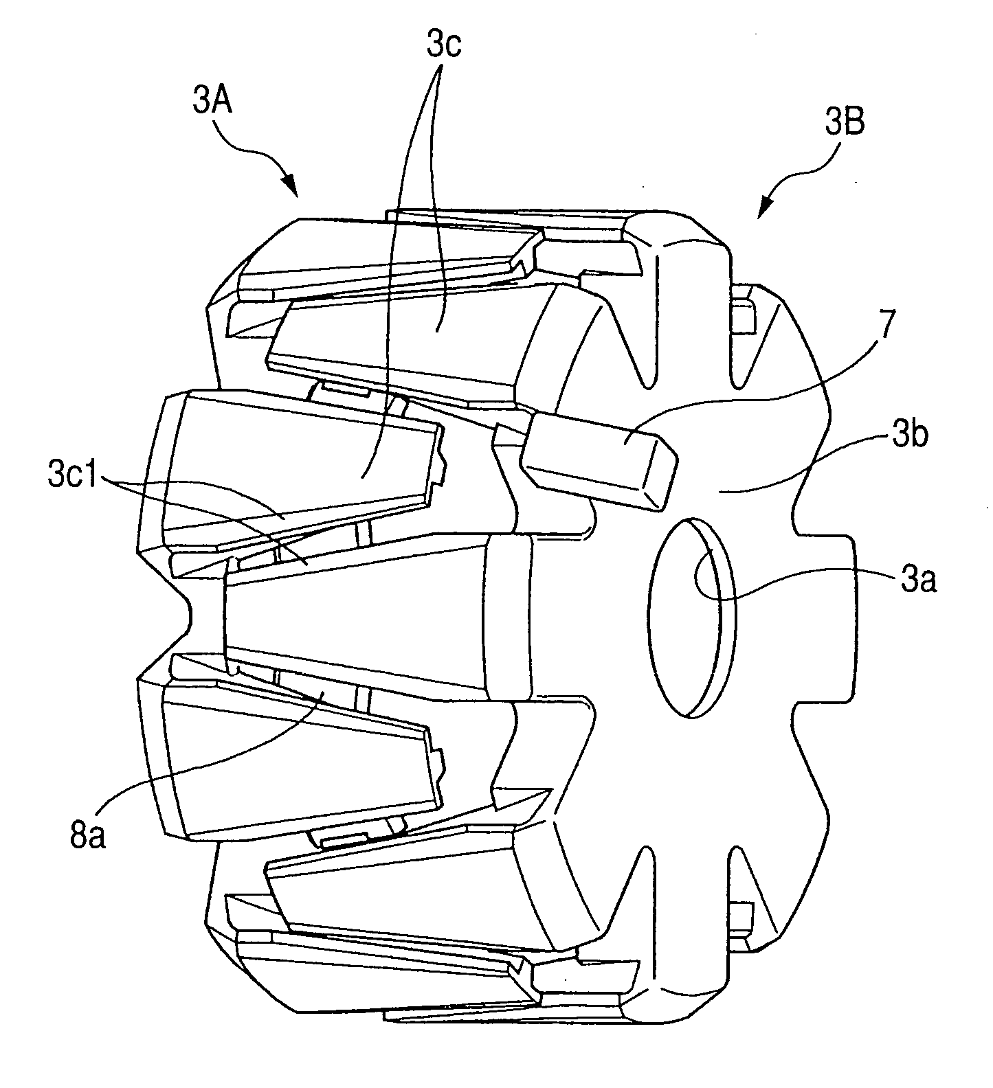
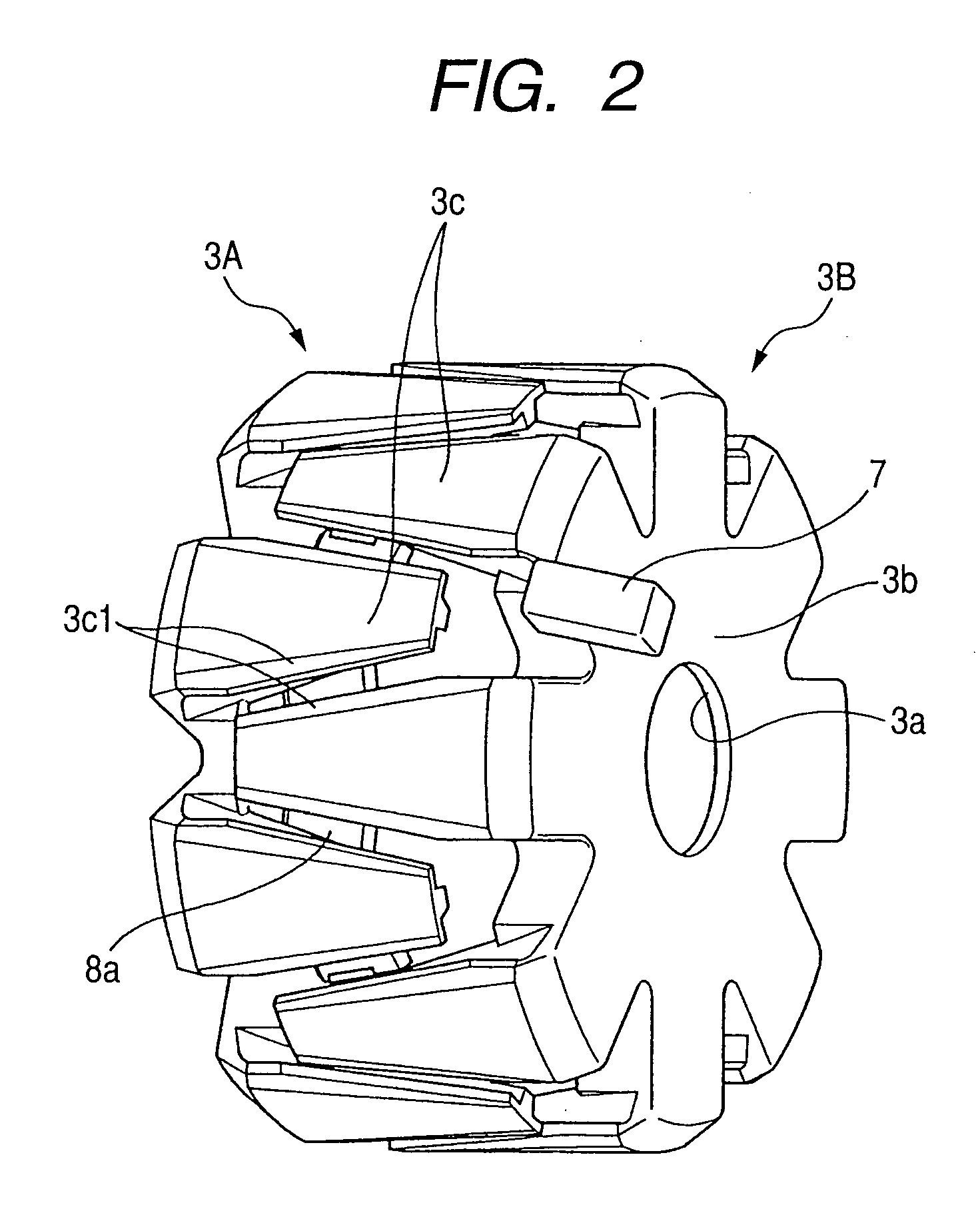
[0016]With the rotor for the electric rotary machine according to the first aspect of the present invention, the permanent magnets may be accommodated in magnet insertion spaces, respectively, each of which is defined with a radial spacing between each of the engaging stop portions formed on the claw-shaped magnetic poles, respectively, and the magnet support ring and a circumferential dimension between the sidewalls of the circumferentially adjacent claw-shaped magnetic poles. In addition, the magnet support ring may be located on inner peripheral sides of the claw-shaped magnetic poles to allow the permanent magnets to be accommodated in the magnet insertion spaces, respectively.
[0017]With such a structure, locating the magnet support ring on the inner peripheral sides of the claw-shaped magnetic poles formed on the pair of field iron cores allows the magnet insertion spaces to be defined for permitting the permanent magnets to be accommodated in the magnet insertion spaces, respectively. That is, none of the permanent magnets is fixedly attached to the magnet support ring and only the permanent magnets can be inserted to the magnet insertion spaces, respectively, for assembly.
[0019]With the rotor for the electric rotary machine according to the first aspect of the present invention, the magnet support ring may preferably include a plurality of circumferentially and equidistantly spaced magnet supporting segments for supporting the plurality of the permanent magnets, respectively, and a plurality of interconnecting segments for interconnecting the plurality of the magnet supporting segments to each other in an annular shape. Each of the magnet supporting segments may preferably have an axial length, extending in line with a longitudinal direction of each permanent magnet, which is longer than a circumferential width of each of the interconnecting segments.
[0020]With such a structure, increasing the length of the magnet supporting segment to be greater than the width of each interconnecting segment enables the permanent magnet to be pressed against the engaging stop portions of the circumferentially adjacent claw-shaped magnetic poles in a stable fashion. Thus, the rotor can be assembled with increased reliability against centrifugal force.
[0022]With the rotor for the electric rotary machine according to the third aspect of the present invention, the magnet supporting segments may preferably have surfaces, on which the permanent magnets are supported, which are formed in flat surfaces, respectively.

Problems solved by technology

Under such a condition, if the permanent magnet is dislocated from a correct position in some degree, then, undue stress occurs on the permanent magnet when inserting the permanent magnet into the space between the circumferentially adjacent claw-shaped magnet poles or during use of the rotor, potentially resulting in damage to the permanent magnet.
This can cause a difficulty to arise in inserting the permanent magnet into the magnet insertion space.
This results in a cause of an increase in production cost.

Method used


Image

  • Rotor for electric rotary machine
  • Rotor for electric rotary machine
  • Rotor for electric rotary machine

Examples


first embodiment

[0125]A first embodiment will be described below with reference to one example of a rotary electric machine as applied to a vehicle alternator.

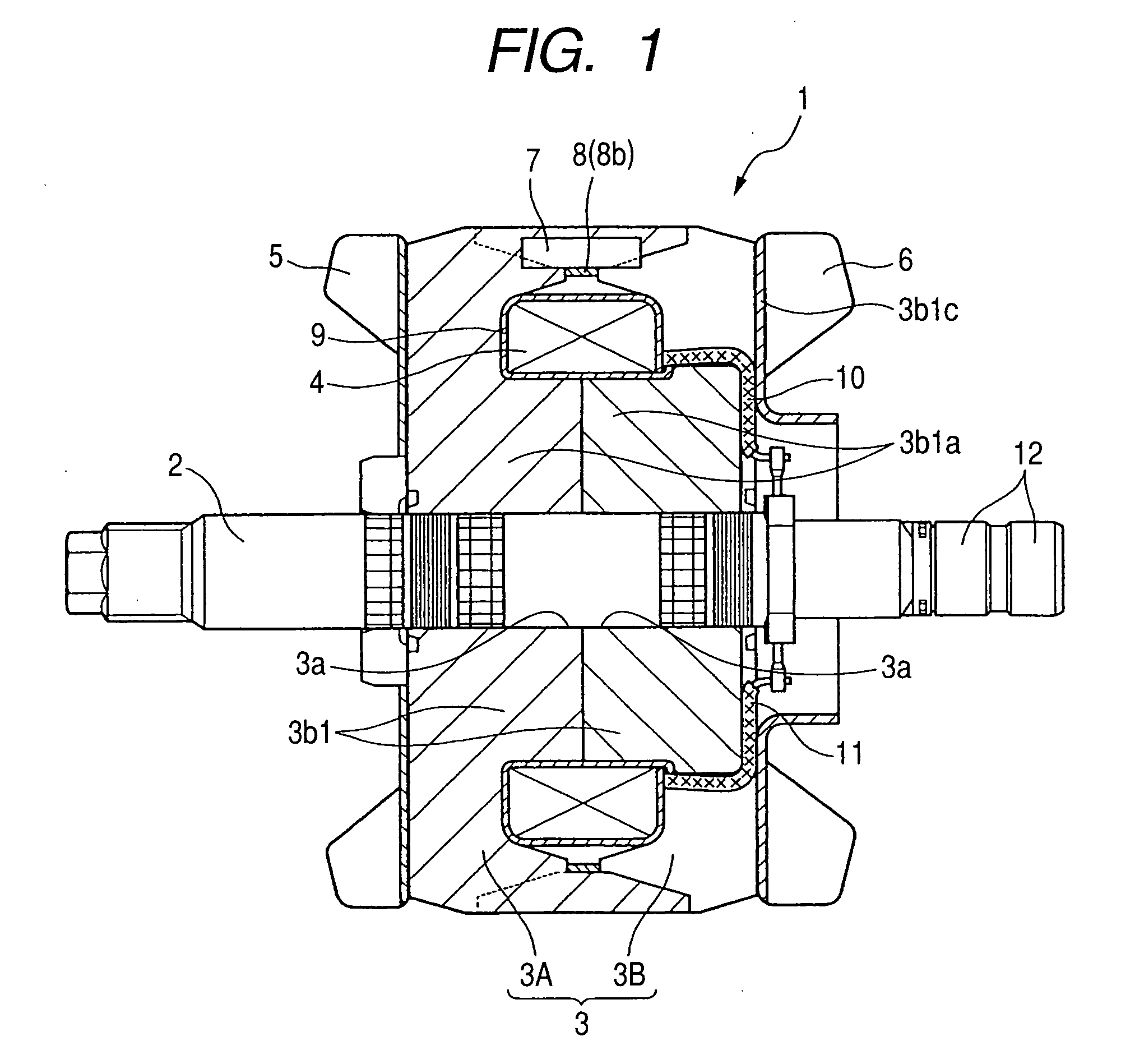
[0126]FIG. 1 is a cross-sectional view of a rotor 1 serving as a field magnet of the vehicle alternator.

[0127]The rotor 1 includes a rotary shaft 2 rotatably supported with a housing (not shown) by means of bearings (not shown), a pair of field iron cores 3 (3A, 3B) fixedly mounted on the rotary shaft 2, a field winding 4 wound on the field iron cores 3, cooling fans 5 and 6 fixedly secured to axially facing end faces of the pair of field iron cores 3, a plurality of permanent magnets (with sixteen pieces with the present embodiment and hereinafter abbreviated as “magnets”) 7 each assembled between each pair of field iron cores 3, and a support ring 8 for supporting the magnets 7 at radially facing inner circumferential areas of the rotor 1.

[0128]The rotary shaft 2 has one axial end (on a left hand side in FIG. 1) carrying thereon a pulley (n...

second embodiment

[0160]FIG. 12 is a plan view showing how the magnets 7 are assembled in place.

[0161]The first embodiment has been described above with reference to an example in which the supporting ring 8 is preliminarily located on the claw-shaped magnetic poles 3c at the inner peripheral sides thereof and, subsequently, the magnets 7 are inserted to the magnet accommodating spaces for assembly. A second embodiment will be described below with reference to another example in which the magnets 7 are assembled before the pair of field iron cores 3 are assembled together.

[0162]First, of the pair of field iron cores 3, either one of these field iron cores 3, i.e., for instance, the supporting ring 8 is located on the claw-shaped magnetic poles 3c of the field core 3A.

[0163]As shown in FIG. 12, in consecutive step, the magnets 7 are inserted to radial compartments each specified between the holder portion 3c1, formed on each claw-shaped magnetic pole 3c, and each magnet supporting segment 8a in a radi...

third embodiment

[0166]FIG. 13 is a cross-sectional view of the claw-shaped magnetic poles 3c, the magnets 7 and a supporting ring 8A.

[0167]With a third embodiment, the magnets 7 are accommodated in holders 15, respectively. Each of the folders 15 is made of non-magnetic material, such as, for instance, stainless steel or resin and the-shaped, and formed in a box-shaped configuration in conformity to each of the holders 15 with which an entire surface of each magnet 7 is encompassed.

[0168]As shown in FIG. 15, the holders 15 have inner peripheral walls whose central areas are formed with radial protrusions 15a to be positioned in a magnet supporting segments 8aA of the supporting ring 8A. Meanwhile, the magnet supporting segments 8aA have positioning hole (apertured portion)s 8a1 to which the protrusions 15a of the holders 15 are brought into fitting engagement. Causing the positioning hole (apertured portion)s 8a1 and the protrusions 15a to be brought into fitting engagement with each other enables ...


PUM

PropertyMeasurementUnit
Lengthaaaaaaaaaa
Widthaaaaaaaaaa
Surface areaaaaaaaaaaa

Abstract

A rotor for an electric rotary machine and a method of manufacturing the same are disclosed wherein none of permanent magnets is fixed to a magnetic supporting segment of a magnet support ring in advance and each permanent magnet is assembled separately of the magnet support ring. Prior to the assembling of the permanent magnets, the magnet support ring is preliminarily located on claw-shaped magnetic poles at inner peripheral sides thereof under a state combined with a pair of field iron cores, after which the permanent magnets are inserted to magnet insertion spaces in longitudinal directions. The rotor includes positioning and restricting means for precluding the occurrence of positional displacement of each permanent magnet with respect to each magnet supporting segment of the magnet support ring.

Description

CROSS REFERENCE TO RELATED APPLICATIONS[0001]This application is related to Japanese Patent Application Nos. 2008-281672 and 2008-310782 filed on Oct. 31, 2008 and Dec. 5, 2008, respectively, the contents of which are hereby incorporated by reference.BACKGROUND OF THE INVENTION[0002]1. Technical Field of the Invention[0003]The present invention relates to rotors for electric rotary machines and, more particularly, to a rotor for an electric rotary machine having permanent magnets each disposed between adjacent claw-shaped magnet poles formed on a pair of field iron cores.[0004]2. Description of the Related Art[0005]In the related art, a technology, disclosed in, for instance, Patent Publication 1 (Japanese Patent Application Publication No. H08-223882), has heretofore been known as an alternator for an automotive vehicle or the like. With such a structure of the related art, a technology has been proposed contemplating the provision of a pair of Lundell type pole cores formed with c...

Claims


Application Information

Patent Timeline
IPC IPC(8): H02K1/28H02K1/27H02K15/03
CPCH02K21/044H02K15/022Y10T29/49012
Inventor KONDO, KOJIHAYASHI, YOSHINORI
Owner DENSO CORP
Learn More