Atomic force microscope apparatus
a microscope and microscope technology, applied in the field ofatomic force microscope equipment, can solve the problems of disadvantageous preclusion of accurate measurements, and achieve the effect of reducing the obtained imag
- Summary
- Abstract
- Description
- Claims
- Application Information
AI Technical Summary
Benefits of technology
Problems solved by technology
Method used
Image

Examples
first embodiment
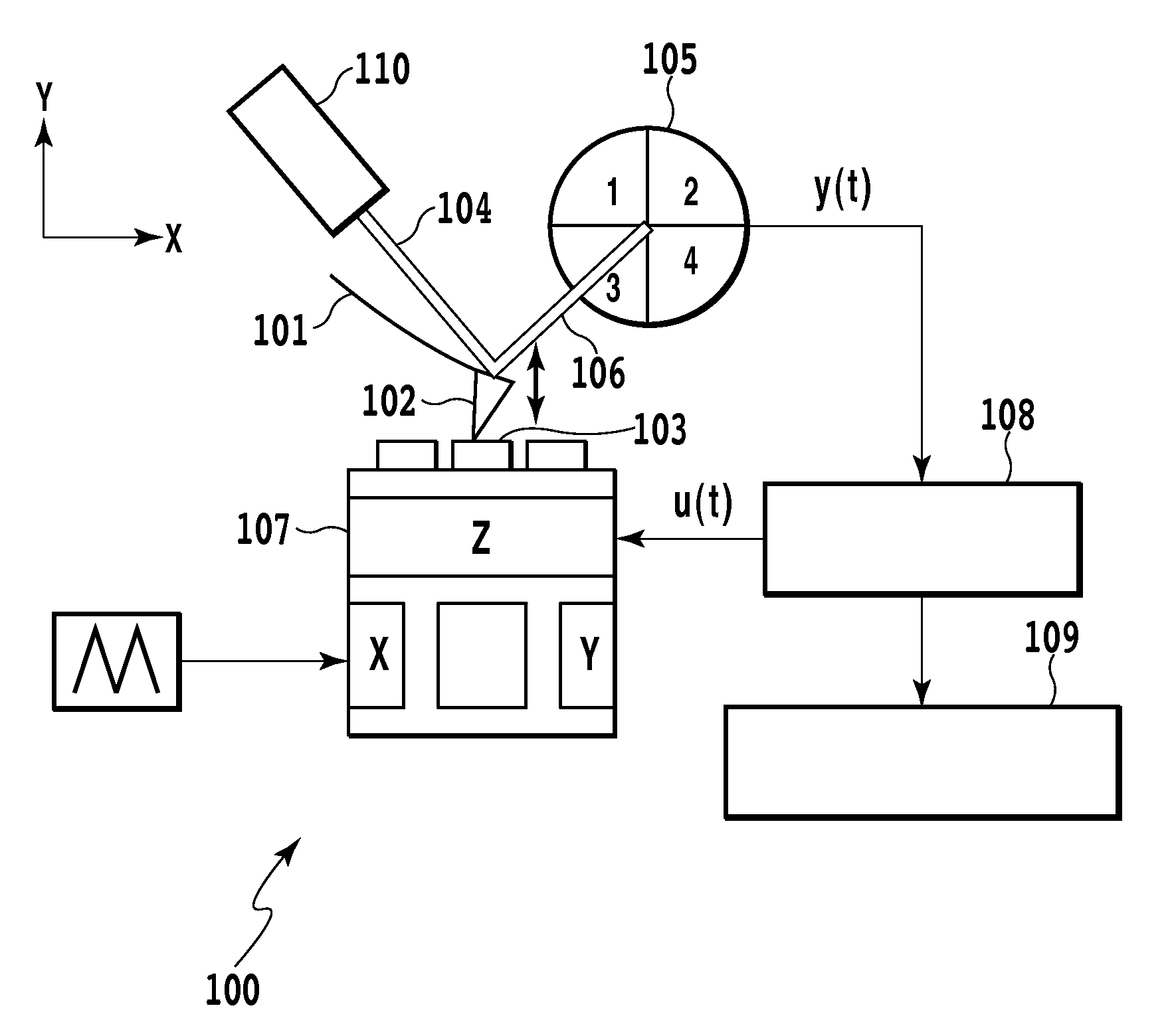
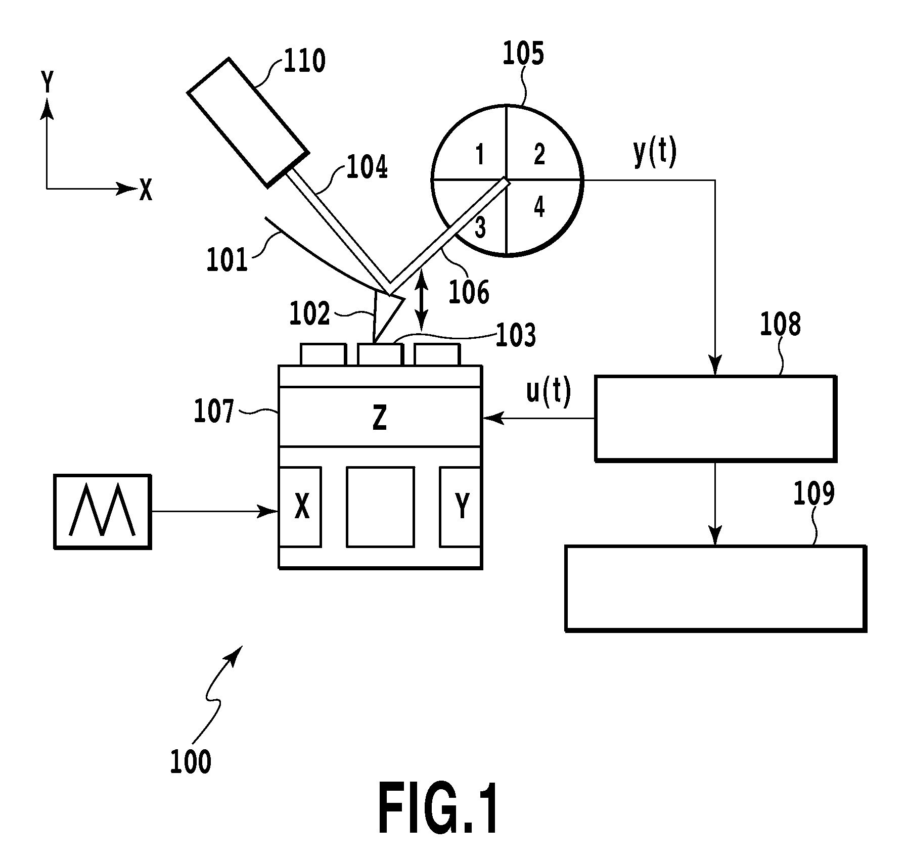
[0146]FIG. 1 is a schematic diagram showing an AFM 100 according to the present invention by way of example. In FIG. 1, in the AFM 100, a probe 102 attached to a cantilever 101 performs scanning along a sample surface 103 to measure deflection of the cantilever 101 caused by an atomic force exerted between the sample surface 103 and the probe 102 as well as distortion of the cantilever 101 caused by a friction force exerted between the sample surface 103 and the probe 102. The structure of the sample surface 103 is measured on a nano-scale.
[0147]In the AFM 100 shown in FIG. 1, laser light provision means 110 allows laser light 104 to obliquely enter the rear surface of the cantilever 101. Then, a change in the reflection angle of the laser light 104 caused by displacement of cantilever 101 resulting from deflection and distortion thereof is detected based on a relative change in the intensity of laser light 106 entering a four-piece photodiode 105. Finally, the AFM 100 can detect th...
second embodiment
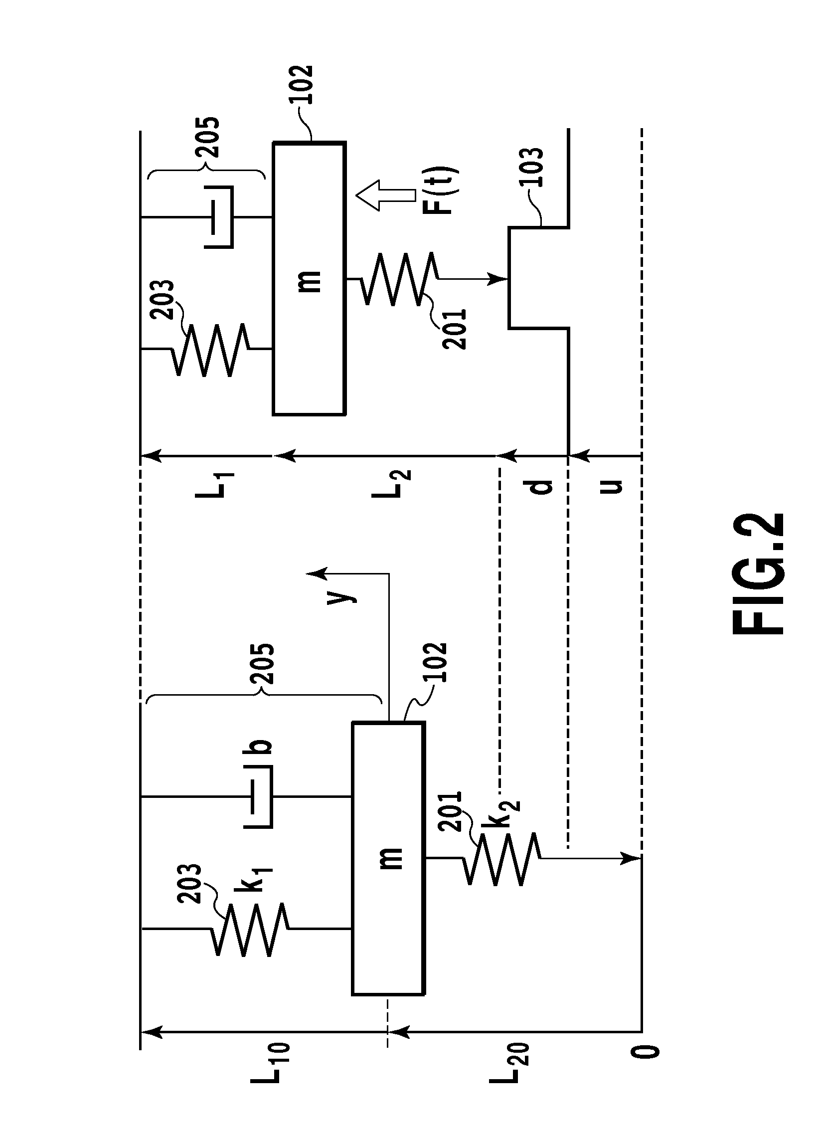
[0222]Also in a second embodiment, a model based on a contact mode for the interaction between a sample surface 103 and the tip 102 of a cantilever is used to give a motion equation for the tip of the cantilever with a mass (m), as shown in formula (1).
[0223]The method described in Non-Patent Document 2 can be used to convert the above-described model into one to which the recesses and protrusions on the sample surface 103 are input. A transfer function for the plant according to the present embodiment is identified as follows according to a method of system identification described in Non-Patent Document 9.
[Expression25]P(s)=7.034×10⁹s2+9219s+1.274×10⁹(17)
[0224]FIGS. 43 and 44 show a comparison of the frequency characteristics of a plant based on formula (17) with frequency characteristics identified by a servo analyzer (manufactured by ONO SOKKI Co., Ltd.). The figures show that the plant identified as shown in formula (17) resonates significantly at 5,590 [Hz] and provides a high...
third embodiment
[0288]As described below, the present embodiment includes a simple identification method for the STLO which uses a low-order model to allow the frequency characteristics of a plant to be easily identified, and an STLO improved by using zeroth-order phase error inverse model (ZPEI).
(Internal Configuration of the AFM)
[0289]The AFM according to the present embodiment is a special model of a JSPM-5200 manufactured by JEOL Ltd. However, this is only an example, and any AFM is applicable provided that the present embodiment can be incorporated into the AFM. Alternatively, dSPACE1104 may be used to modify the control mechanism for the AFM so that the control mechanism allows the present embodiment to be implemented.
[0290]FIG. 3 is a block diagram showing the flow of signals inside the AFM according to the present embodiment.
[0291]As shown by reference numeral 310 in FIG. 3, when a sample surface 103 is scanned, the displacement of the tip 102 of the cantilever is detected by a PD (four-pie...
PUM
 Abstract
Description
Claims
Application Information
 - R&D
- Intellectual Property
- Life Sciences
- Materials
- Tech Scout
- Unparalleled Data Quality
- Higher Quality Content
- 60% Fewer Hallucinations
Browse by: Latest US Patents, China's latest patents, Technical Efficacy Thesaurus, Application Domain, Technology Topic, Popular Technical Reports.
© 2025 PatSnap. All rights reserved.Legal|Privacy policy|Modern Slavery Act Transparency Statement|Sitemap|About US| Contact US: help@patsnap.com