Assisted selective growth of highly dense and vertically aligned carbon nanotubes

a carbon nanotube, vertical alignment technology, applied in waveguides, waveguide type devices, transportation and packaging, etc., can solve the problems of high density and ordered alignment of carbon nanotubes, insufficient cnt yield, density, alignment, uniformity and pattern formation, etc., to improve cnt yield, film coverage and uniformity.

Inactive Publication Date: 2010-05-13
INTELLECTUAL VENTURES HLDG 40
View PDF15 Cites 17 Cited by
  • Summary
  • Abstract
  • Description
  • Claims
  • Application Information

AI Technical Summary

Benefits of technology

[0005]One advantage of the present invention is that it improves CNT yield, film coverage and uniformity. Another

Problems solved by technology

However, to integrate with conventional chips based on silicon technology, highly dense and ordered aligned CNTs are needed.
The quality of the CNTs in terms of yield, film coverage, density, alignment, uniformity and pattern formation have not been sufficient to meet the requirements of microelectronics app

Method used


Image

  • Assisted selective growth of highly dense and vertically aligned carbon nanotubes
  • Assisted selective growth of highly dense and vertically aligned carbon nanotubes
  • Assisted selective growth of highly dense and vertically aligned carbon nanotubes

Examples


Embodiment Construction

[0015]In the following description, numerous specific details are set forth such as specific device configurations, etc. to provide a thorough understanding of the present invention. However, it will be obvious to those skilled in the art that the present invention may be practiced without such specific details.

[0016]Refer now to the drawings wherein depicted elements are not necessarily shown to scale and wherein like or similar elements are designated by the same reference numeral through the several views.

[0017]Referring to FIGS. 6A-6E, in embodiments of the present invention as described hereafter, carbon nanotubes may be grown using thermal catalytic chemical vapor deposition (CCVD) on a thick SiO2 film (e.g., 300 nm) thermally grown on a Si wafer (601 in FIG. 6A). Substrate materials are not limited to SiO2. Other commonly used substrates may be used, such as silicon, aluminum oxide, quartz, glass, and various metal materials. As further described hereafter, a Fe / Ta bilayer pr...


PUM

PropertyMeasurementUnit
Contact angleaaaaaaaaaa
Structureaaaaaaaaaa
Contact angleaaaaaaaaaa

Abstract

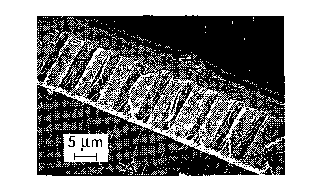
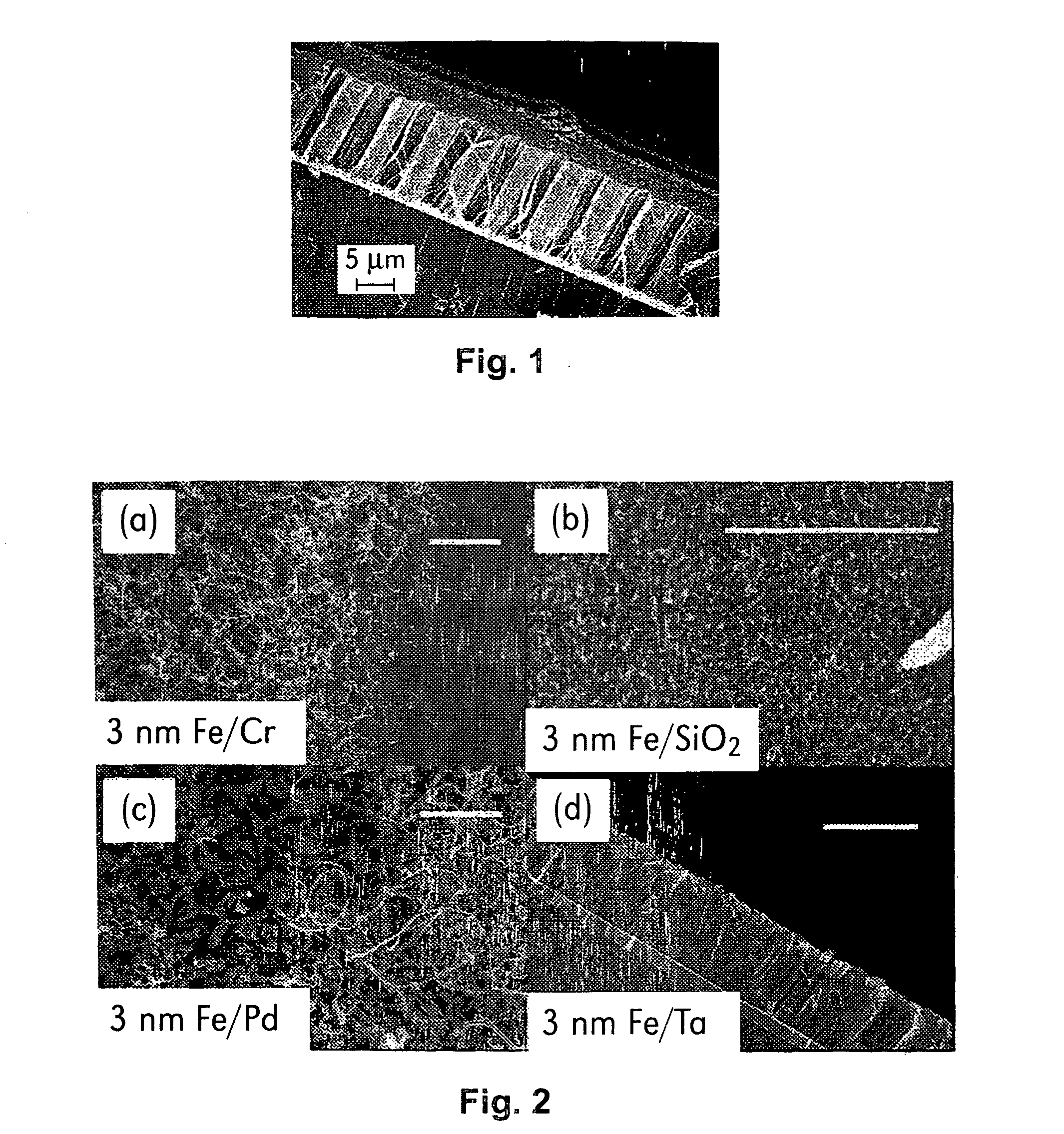
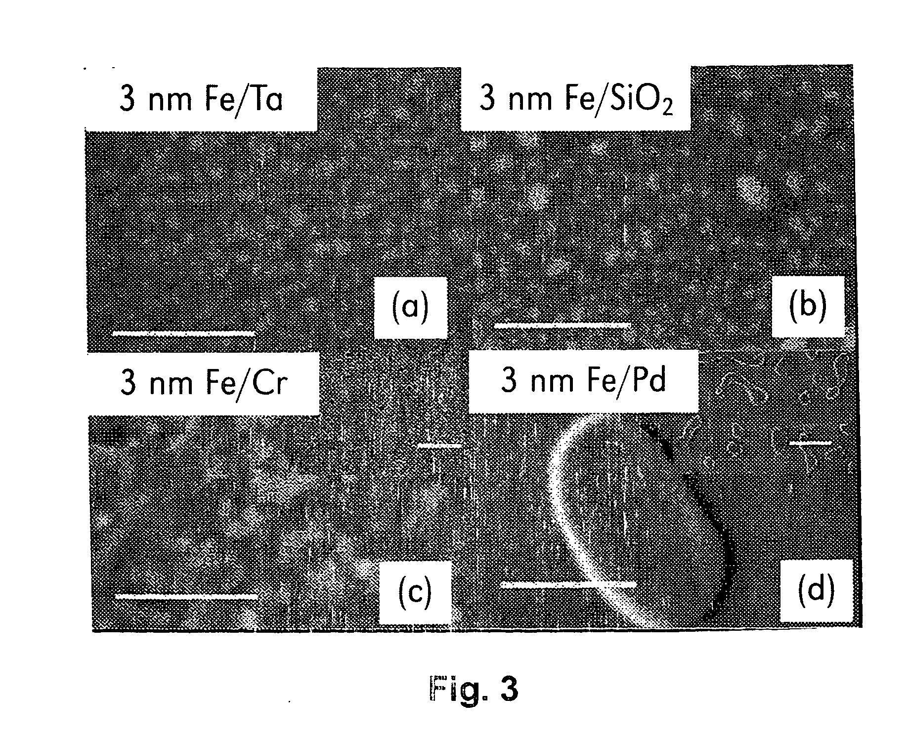
The selective growth of vertically aligned, highly dense carbon nanotube (CNT) arrays using a thermal catalytic chemical vapor deposition (CCVD) method via selection of the supporting layer where the thin catalyst layer is deposited on. A thin iron (Fe) catalyst deposited on a supporting layer of tantalum (Ta) yielded CCVD growth of the vertical dense CNT arrays. Cross-sectional transmission electron microscopy revealed a Vollmer-Weber mode of Fe island growth on Ta, with a small contact angle of the islands controlled by the relative surface energies of the supporting layer, the catalyst and their interface. The as-formed Fe island morphology promoted surface diffusion of carbon atoms seeding the growth of the CNTs from the catalyst surface.

Description

TECHNICAL FIELD[0001]The present invention relates in general to the growth of carbon nanotubes in a selective manner.BACKGROUND INFORMATION[0002]Carbon nanotubes (CNTs) have been proposed as building blocks for the future generation of computer chips due to their high thermal conductivity, large current-carrying capacity, and excellent physical and chemical stabilities. However, to integrate with conventional chips based on silicon technology, highly dense and ordered aligned CNTs are needed. Although CNTs have been produced by many different methods, most of such efforts to control CNT growth have been achieved by adjusting the precursor gases and their flow rates, synthesis pressure and temperature, external bias, and catalyst compositions and sizes. The quality of the CNTs in terms of yield, film coverage, density, alignment, uniformity and pattern formation have not been sufficient to meet the requirements of microelectronics applications. So far, the integration of CNT structu...

Claims


Application Information

Patent Timeline
IPC IPC(8): H01P1/20C23C16/26C03C17/38
CPCB82Y30/00B82Y40/00Y10T428/12625C01B2202/08C01B31/0233C01B32/162
Inventor WANG, YUNYUHO, PAUL S.SHI, LIYAO, ZHEN
Owner INTELLECTUAL VENTURES HLDG 40
Why Eureka
Try Eureka