Structure for improving the voltage difference of a connector

a technology of voltage difference and connector, which is applied in the direction of connection contact material, two-part coupling device, connection device connection, etc., can solve the problems of high cost, slow assembly speed, and increase of electromagnetic interference (emi) of voltage difference, so as to improve the voltage difference of the connector, reduce manpower and working time, and reduce assembly time

Inactive Publication Date: 2010-05-20
MUSTANG IND
View PDF23 Cites 7 Cited by
  • Summary
  • Abstract
  • Description
  • Claims
  • Application Information

AI Technical Summary

Benefits of technology

[0013]One particular aspect of the present invention is to provide a structure for improving the voltage difference of a connector that overcomes the drawbacks of the c

Problems solved by technology

Therefore, the voltage difference generates an increase of electromagnetic interference (EMI).
1. Comparatively more manpower is necessary if the manual soldering method is required. The assembly speed is slow, the cost is high.
2. When the soldering operation is performed and the worker needs to rotate the communication connector and the enclosure to change the soldering direction and location, the required soldering time and manpower is further prolonged.
3. The fake-solder symptom may occur due to the human factor of carelessness, inferior skill, or the tin being not smoothly pulled.
4. Due to worker operation mistake, it is easy to make the high temperature soldering iron

Method used


Image

  • Structure for improving the voltage difference of a connector
  • Structure for improving the voltage difference of a connector
  • Structure for improving the voltage difference of a connector

Examples


Embodiment Construction

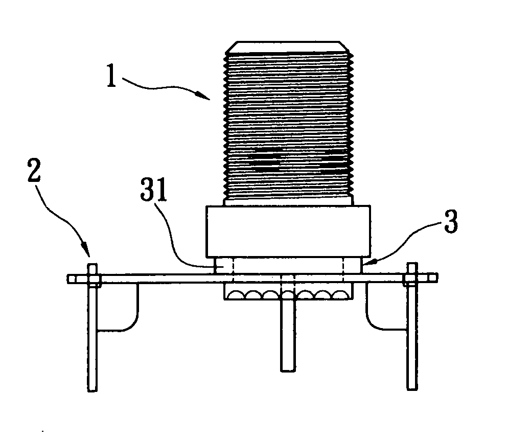
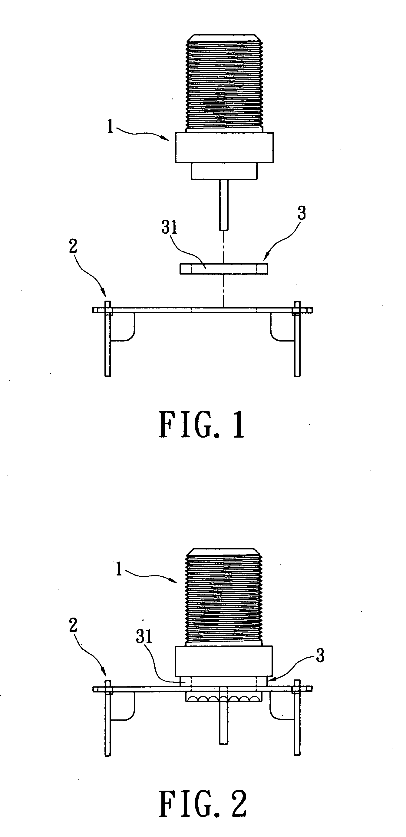
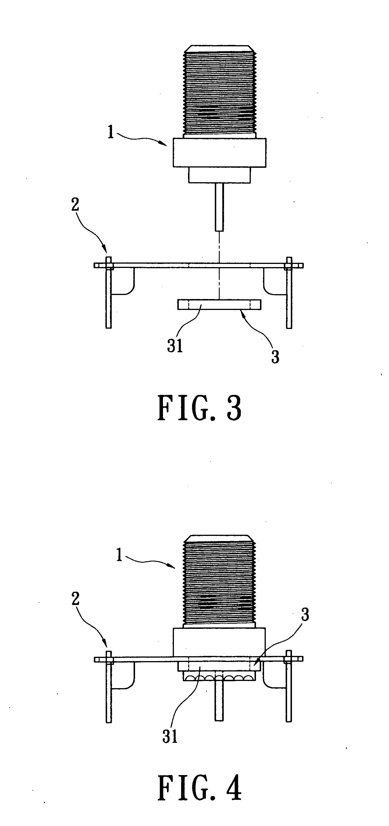
[0041]Reference is made to FIGS. 1-4. The structure for improving the voltage difference of a connector of the present invention includes a communication connector 1, an enclosure 2, and a conducting element 3. The type of the communication connector 1 is not limited to a specific one. The communication connector 1 can be an F connector manufactured by turning or free-cutting, a PAL connector manufactured by turning, free-cutting, pipe-cutting, or deep-drawing, or other connector. The enclosure 2 is a metallic frame. The enclosure 2 is assembled with communication connector 1.

[0042]The conducting element 3 is a conductive metal or material, such as copper, aluminum, tin, iron, tin-strip, conducting gasket, or conductive glue, etc. In this embodiment, the conductive element 3 is a non-sticky conductive gasket 31. The conductive gasket 31 is a conductive metal or material and is non-sticky. The shape of the raw material can be flake-shaped, strip-shaped, board-shaped, roll-shaped, etc...


PUM


Abstract

A structure for improving the voltage difference of a connector includes a communication connector, an enclosure, and a conducting gasket. The communication connector is assembled with the enclosure. The conducting gasket is located and conducted at the connection area of the communication connector and the enclosure. Thereby, the conductivity of the communication connector and the enclosure is increased and the voltage difference is improved. Furthermore the connector does not require traditional manual welding for connection; thereby manufacturing time and cost are reduced.

Description

BACKGROUND OF THE INVENTION[0001]1. Field of the Invention[0002]The present invention relates to a structure for improving the voltage difference of a connector; in particular, the present invention relates to a structure for improving the voltage difference of a connector that improves the conductivity of a communication connector and an enclosure so as to improve the voltage difference.[0003]2. Description of Related Art[0004]A communication connector and an enclosure (or named as tuner, can, RF can, iron shell, or lower cover) are conventionally assembled by riveting or soldering. Because the communication connector and the enclosure are independently formed, there is a tiny gap on the contacting surface when the communication connector and the enclosure are assembled. Therefore, the voltage difference generates an increase of electromagnetic interference (EMI).[0005]Conventionally, the voltage difference is improved by manually soldering the riveting area. A worker needs to use ...

Claims


Application Information

Patent Timeline
IPC IPC(8): H01R24/00
CPCH01R4/02H01R4/64H01R2103/00H01R24/52H01R13/73
Inventor LIU, TING-PAN
Owner MUSTANG IND
Why Eureka
Try Eureka