
Guided mode resonance solar cell

a solar cell and guided mode technology, applied in the field of guided mode resonance solar cells, can solve the problems of insufficient absorption of the gap energy between the valence band, the cost of silicon becoming relatively expensive, and the increase in silicon quantity, etc., to achieve the effect of facilitating the capture of ligh

Inactive Publication Date: 2010-05-27
NAT CENT UNIV
View PDF1 Cites 38 Cited by
  • Summary
  • Abstract
  • Description
  • Claims
  • Application Information

AI Technical Summary

Benefits of technology

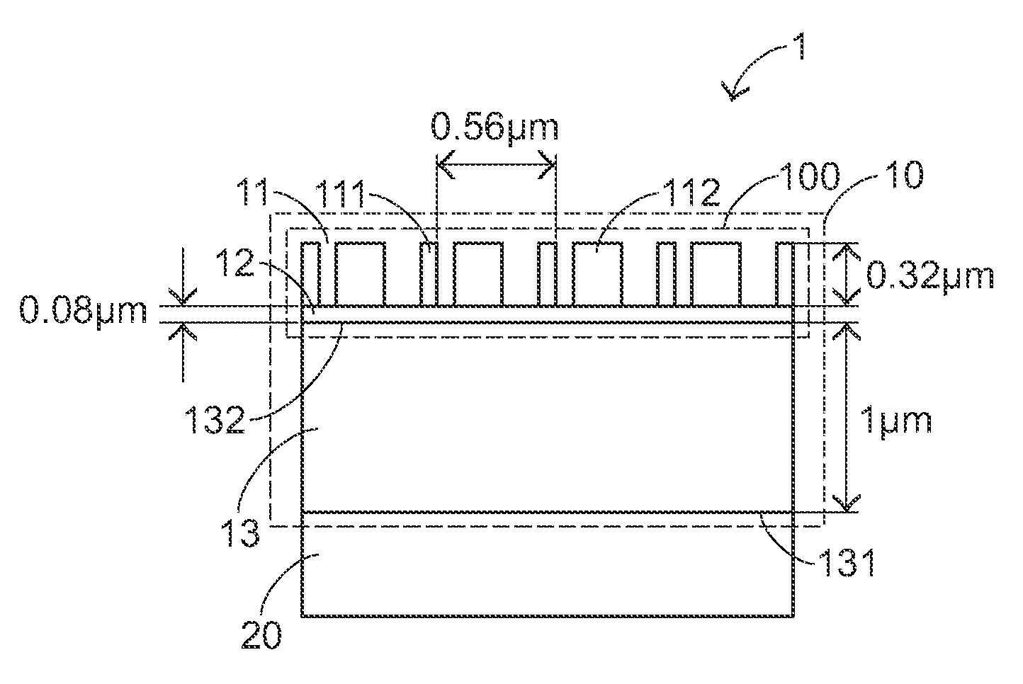
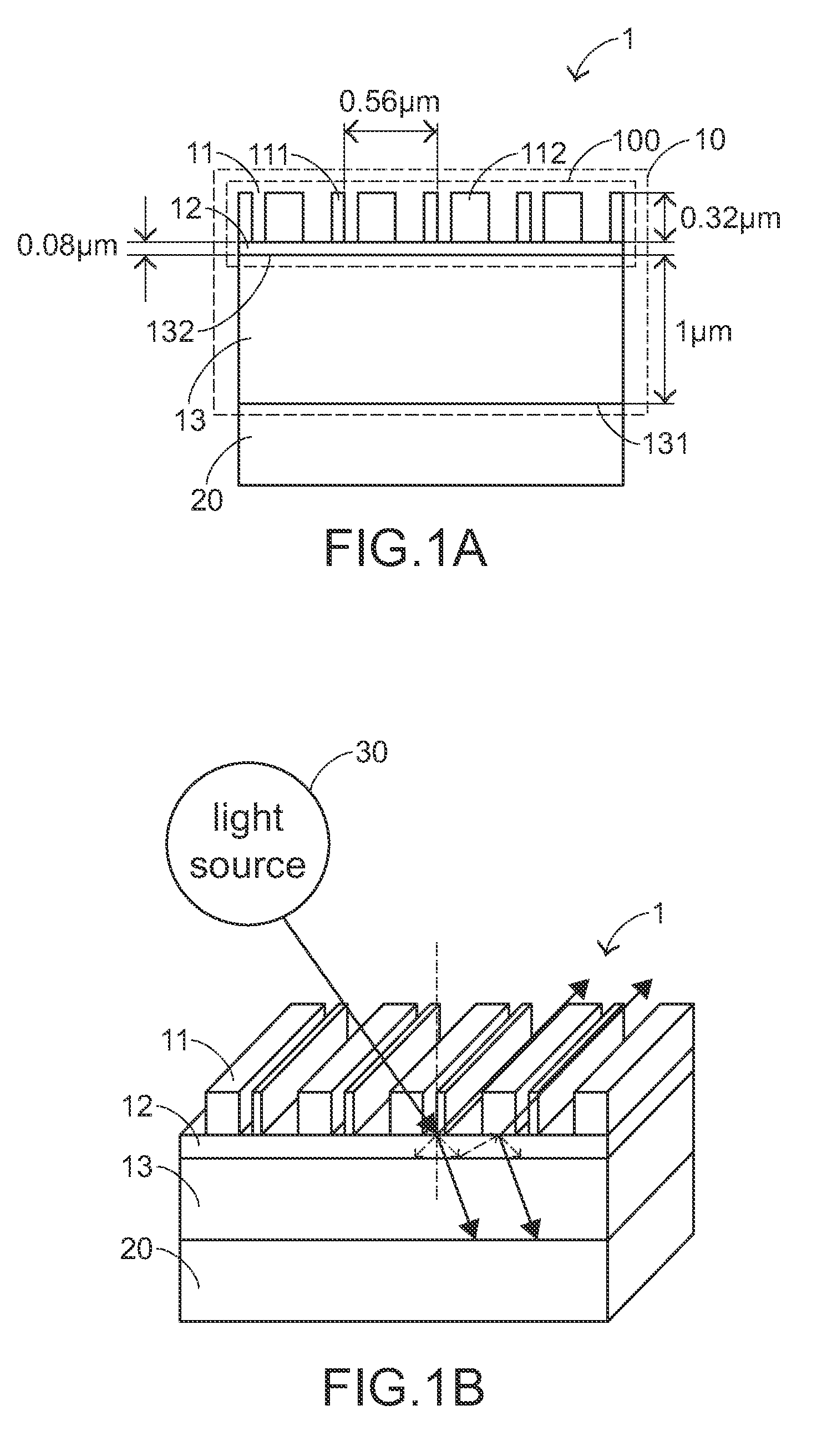
[0008]The present invention provides a guided mode resonance solar cell by combining a guided mode resonance (GMR) unit with a known TF-Si solar cell body, thereby elongating the optical path length, increasing the light absorption, and enhancing the energy conversion efficiency.
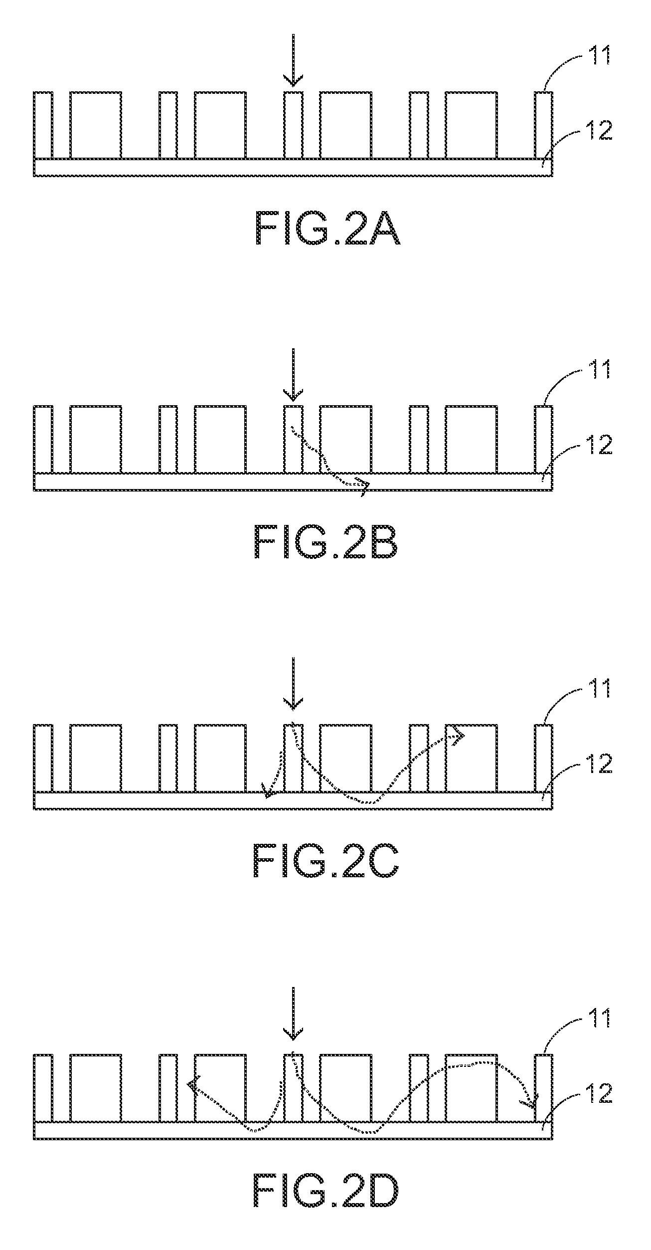
[0010]In accordance with another aspect of the present invention, there is provided a guided mode resonance solar cell. The guided mode resonance solar cell includes a solar cell body and a guided mode resonance unit. The solar cell body is used for converting optical energy into electrical energy. The guided mode resonance unit is formed on the solar cell body, and includes a grating structure and a waveguide structure. The grating structure includes multiple sub-wavelength light pillars. When a light emitted from a light source is incident onto the grating structure, a resonant of the light occurs in the grating structure to facilitate trapping the light in the waveguide structure and elongating an optical path length.

Problems solved by technology

With the maturity of the semiconductor fabricating industries, the demand quantity of silicon gradually increases and thus the cost of silicon becomes relatively costly.
A major challenge in achieving high efficiency TF-Si solar cells is the insufficient absorption for the gap energy between the valence band and the conduction band.
The insufficient absorption leads to low energy conversion efficiency.
In addition, the light absorbed by the planar thin-film silicon can only be reflected by or transmitted through the planar thin-film silicon.
It is found that the insufficient absorption is resulted from small thickness of the thin-film silicon.
This problem is especially severe in the near infrared spectrum (about 0.9 μm to 1 μm).
As the incident wavelength is away from the specific wavelength, the effect of energy coupling will decay and thus the optical path length fails to be effectively elongated by surface textures.
Moreover, as the diffracted wave is reflected by the silicon material, a part of wave will evanesce from the surface textures and can't be returned back to the silicon material again.

Method used


Image

  • Guided mode resonance solar cell
  • Guided mode resonance solar cell
  • Guided mode resonance solar cell

Examples


Embodiment Construction

[0015]The present invention will now be described more specifically with reference to the following embodiments. It is to be noted that the following descriptions of preferred embodiments of this invention are presented herein for purpose of illustration and description only. It is not intended to be exhaustive or to be limited to the precise form disclosed.

[0016]The present invention provides a guided mode resonance solar cell. The guided mode resonance solar cell combines a guided mode resonance (GMR) unit with a known TF-Si solar cell body. The guided mode resonance solar cell of the present invention has an elongated optical path length and increased light dwelling time, so that the energy conversion efficiency and the light-trapping effect are both enhanced. The term “guided mode resonance (GMR)” is a phenomenon indicating that the light passing through gratings irregularly diffracts into a waveguide layer. That is, the light passing through gratings tends to couple into the wa...


PUM


Abstract

A guided mode resonance solar cell includes a solar cell body and a guided mode resonance unit. The solar cell body is used for converting optical energy into electrical energy. The guided mode resonance unit is formed on the solar cell body, and includes a grating structure and a waveguide structure. The grating structure includes multiple sub-wavelength light pillars. When a light emitted from a light source is incident onto the grating structure, a resonant of the light occurs in the grating structure to facilitate trapping the light in the waveguide structure and elongating an optical path length.

Description

FIELD OF THE INVENTION[0001]The present invention relates to a guided mode resonance solar cell, and more particularly to a guided mode resonance solar cell with enhanced energy conversion efficiency.BACKGROUND OF THE INVENTION[0002]Recently, the ecological problems resulted from fossil fuels such as petroleum and coal have been greatly aware all over the world. Consequently, there are growing demands on clean energy. Among various alternative energy sources, a solar cell is expected to replace fossil fuel as a new energy source because it provides clean energy without depletion and is easily handled. A solar cell can convert sunlight directly into electrical energy, which is fed into various power modules for applications.[0003]Nowadays, the technologies and researches relating to applications of the solar cell in producing electricity for practical use are gaining popularity. The solar cell mainly captures energy from sunlight. The solar cell absorbs the visible part of the solar ...

Claims


Application Information

Patent Timeline
IPC IPC(8): H01L31/00
CPCG02B6/124Y02E10/50H01L31/02168G02B6/34
Inventor WU, MOUNT-LEARNCHANG, JENQ-YANGLEE, YUN-CHIHHUANG, CHIAN-FU
Owner NAT CENT UNIV
Learn More