Transparent electronics based on transfer printed carbon nanotubes on rigid and flexible substrates

a technology of transfer printed carbon nanotubes and transparent electronics, which is applied in the direction of nanotechnology, electrical equipment, semiconductor devices, etc., can solve the problems of ttfts fabricated in these cases that exhibit rather moderate mobilities, oxide-based ttfts generally limited to n, and the development of high-performance transparent p-type transistors. , to achieve the effect of high carrier mobility

Inactive Publication Date: 2010-05-27
UNIV OF SOUTHERN CALIFORNIA
View PDF4 Cites 54 Cited by
  • Summary
  • Abstract
  • Description
  • Claims
  • Application Information

AI Technical Summary

Benefits of technology

[0011]Embodiments of the present invention provide methods and devices for transparent electronics. According to an embodiment, transparent electronics are provided based on transfer printed aligned carbon nanotubes. The aligned carbon nanotubes-based transparent electronics can be disposed on both rigid and flexible substrates. Methods are provided to enable highly aligned single-walled carbon nanotubes (SWNTs) to be used in transparent electronics for achieving high carrier mobility while using low-temperature processing.

Problems solved by technology

However, TTFTs fabricated in these cases usually exhibit rather moderate mobilities.
In addition, the oxide based TTFTs have generally been limited to n-type transistors.
Indeed, the development of high performance transparent p-type transistors, which is an essential element in CMOS, still remains a great challenge.

Method used


Image

  • Transparent electronics based on transfer printed carbon nanotubes on rigid and flexible substrates
  • Transparent electronics based on transfer printed carbon nanotubes on rigid and flexible substrates
  • Transparent electronics based on transfer printed carbon nanotubes on rigid and flexible substrates

Examples


example 1

Fabrication of Transparent Aligned Nanotube Transistors on Glass and PET

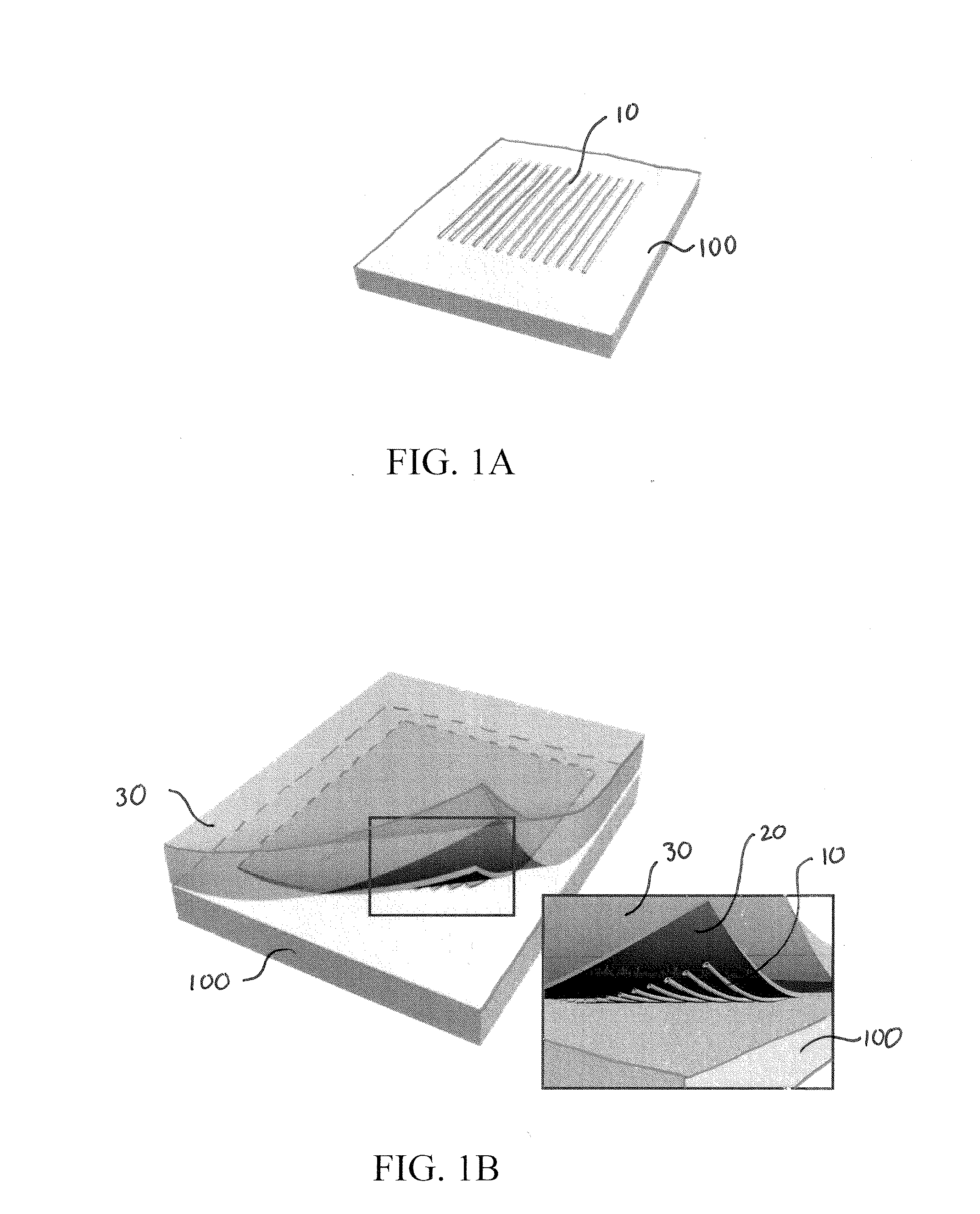
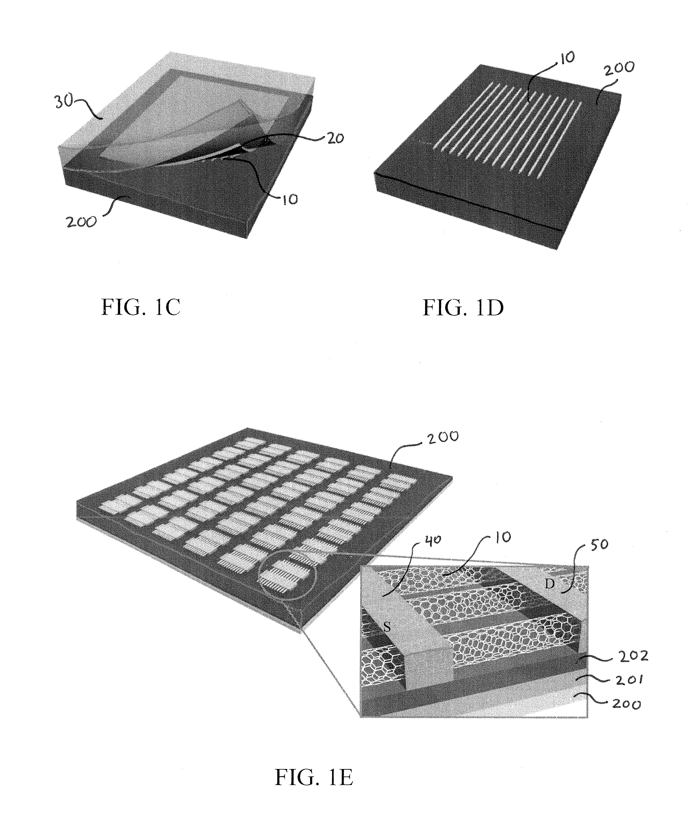
[0063]The aligned nanotubes were first grown on quartz substrates using chemical vapor deposition (CVD). For the specific examples, the aligned SWNTs were grown using chemical vapor deposition at 900° C. with gas flow of 2500 sccm CH4, 10 sccm C2H4, and 600 sccm H2. The transfer started by coating as-grown aligned SWNTs on a quartz substrate with a 100 nm thick Au film. The Au film was coated onto the SWNTs by an evaporation process using an e-beam evaporator. Revalpha thermal tape (specifically, #3198M from Nitto Denko), which is adhesive at room temperature but loses adhesion above 120° C., was pressed onto the Au film, and then peeled off slowly, resulting in picking up the nanotube / Au film. The thermal tape / Au film / aligned SWNT film was placed onto a target substrate with an ITO back gate and a SU-8 dielectric layer, and the whole structure was heated up to 130° C. on a hot plate to detach the thermal tape. ...

example 2

Performance of Aligned SWNT TTFTs on Glass

[0067]A glass substrate with an array of devices fabricated in accordance with EXAMPLE 1, above, was used to test the performance of aligned SWNT TTFTs on glass. These transistors have aligned nanotubes as the active channel with channel widths of 10, 20, 50, 100, and 200 μm and channel lengths of 4, 10, 20, 50, and 100 μm. The ITO film on glass was used as the back gate, the 2 μm thick SU-8 was used as the gate dielectric, and the two source / drain contact material structures: 1 nm Au / 100 nm ITO and 100 nm ITO were used for comparison. FIG. 9A shows measured values comparing the transparency of the devices based on the source / drain contact material structures. As shown in FIG. 9A, the devices with Au / ITO contacts had a transmittance of ˜80% in visible light (400˜800 nm). Compared with the devices using only ITO as the contacts, the transmittance decreased about 5% due to the thin Au layer. The performance of the devices having the Au / ITO con...

example 3

Performance of Aligned SWNT TTFTs on PET

[0072]Fully transparent and flexible aligned SWNTs devices using PET substrates were also fabricated in accordance with EXAMPLE 1 to test the performance of aligned SWNT TTFTs on a flexible substrate. For these tests, devices having the ITO back gate, 2 μm thick SU-8 gate dielectric, and ITO source and drain contact material were fabricated. FIG. 10A shows a plot of the transmittance of the transparent, flexible devices. The optical transmission is ˜80% in the 350-1200 nm wavelength range. To evaluate the flexibility of the devices, Ids−Vg measurements were performed under bending of the substrates with different angles and the plots are shown in FIG. 10B. The Ids−Vg curves correspond to a device bended for 0°, 30°, 60°, 90°, and 120°, respectively, with a channel length of 10 μm and width of 200 μm. The transconductance and on-current of the device at each bending angle were extracted from these curves, and were plotted in FIG. 10C. As illust...


PUM

PropertyMeasurementUnit
transmittanceaaaaaaaaaa
angleaaaaaaaaaa
widthaaaaaaaaaa

Abstract

Methods and devices for transparent electronics are disclosed. According to an embodiment, transparent electronics are provided based on transfer printed carbon nanotubes that can be disposed on both rigid and flexible substrates. Methods are provided to enable highly aligned single-walled carbon nanotubes (SWNTs) to be used in transparent electronics for achieving high carrier mobility while using low-temperature processing. According to one method, highly aligned nanotubes can be grown on a first substrate. Then, the aligned nanotubes can be transferred to a rigid or flexible substrate having pre-patterned gate electrodes. Source and drain electrodes can be formed on the transferred nanotubes. The subject devices can be integrated to provide logic gates and analog circuitry for a variety of applications.

Description

CROSS-REFERENCE TO RELATED APPLICATION[0001]This application claims the benefit of U.S. 61 / 117,519, filed on Nov. 24, 2008, which is hereby incorporated by reference in its entirety (including all tables, figures, and other associated data).[0002]The subject invention was made with government support under Grant Nos. CCF-0726815 and CCF-0702204 awarded by the National Science Foundation and Contract No. 2003-NT-1107 awarded by the Center on Functional Engineered and Nano Architectonics. The government has certain rights in the invention.BACKGROUND OF THE INVENTION[0003]Transparent electronics is an emerging technology for the realization of invisible devices and circuits for the next generation of optoelectronic devices and other electronics involving printing, large areas, low cost, flexibility, wearability, and fashion and design Central to the realization of transparent electronics is the development of transparent thin-film transistors (TTFTs). Of interest to current research ar...

Claims


Application Information

Patent Timeline
Patent Type & Authority Applications(United States)
IPC IPC(8): H01L29/66H01L21/336
CPCB82Y10/00H01L51/003H01L51/0545H01L51/0541H01L51/0048H10K71/80H10K85/221H10K10/466H10K10/464
Inventor ZHOU, CHONGWUISHIKAWA, FUMIAKICHANG, HSIAO-KANGRYU, KOUNGMIN
Owner UNIV OF SOUTHERN CALIFORNIA
Why Eureka
Try Eureka