Thermal diffusion sheet and method for mounting the same

a technology of diffusion sheet and thermal diffusion plate, which is applied in the direction of paper/cardboard containers, semiconductor/solid-state device details, other domestic articles, etc., can solve the problems of reducing the adhesive strength, short circuit, and brittleness of the graphite sheet itself, and achieves reliable transfer of heat to the radiator plate, good thermal conductivity, and low cost

Inactive Publication Date: 2010-06-03
FUJI POLYMER INDUSTRIES CO LTD
View PDF9 Cites 27 Cited by
  • Summary
  • Abstract
  • Description
  • Claims
  • Application Information

AI Technical Summary

Benefits of technology

[0015]The thermal diffusion sheet of the present invention includes the thermally conductive adhesive layers formed directly on both surfaces of the graphite sheet, has a structure in which the graphite sheet is sealed by attaching the thermally conductive adhesive layer that is larger than the graphite sheet and has a good thermal conductivity in the plane direction to the radiator plate, and can transfer heat to the radiator plate reliably at a low cost. When the thermal diffusion sheet is affixed to the radiator plate, the end faces of the graphite sheet are sealed with the thermally conductive adhesive layer. Therefore, no graphite powder comes off or falls from the end faces of the graphite sheet even after the mounting of the thermal diffusion sheet. This can eliminate the possibility of a short circuit while the thermal diffusion sheet is mounted on an electric circuit. Thus, it is possible to provide a reliable thermal diffusion sheet.

Problems solved by technology

The graphite sheet itself is brittle and cannot be handled easily.
In the case of a semiconductor mounted on an electric circuit, because of the electrical conductivity as well as the brittleness of the graphite sheet, graphite powder may come off the graphite sheet, fall on the electric circuit, and cause a short circuit.
Thus, the adhesive strength is reduced due to aging deterioration.
In particular, when an adhesive layer is formed directly on the graphite sheet, the phenomenon of reducing the adhesive strength due to aging deterioration is prominent.
Moreover, the double-sided tape and the adhesive are likely to have a low thermal conductivity.
Therefore, even if the graphite sheet has a high thermal conductivity in the plane direction, such a low thermal conductivity of the material, in which heat is transferred before reaching the graphite sheet, is not desirable for the efficiency of “heat transfer”.
In the conventional technology, the double-sided tape, the adhesive, and the insulating film are likely to have a low thermal conductivity, and even if the graphite sheet with a high thermal conductivity in the plane direction is used, such a low thermal conductivity of the material, in which heat is transferred before reaching the graphite sheet, is a problem in the efficiency of “heat transfer”.

Method used


Image

  • Thermal diffusion sheet and method for mounting the same
  • Thermal diffusion sheet and method for mounting the same
  • Thermal diffusion sheet and method for mounting the same

Examples


examples

[0047]Hereinafter, the present invention will be described in detail by way of examples. The present invention is not limited to the following examples.

[0048]The thermally conductive adhesive layers were prepared in the following manner.

[0049](Thermally Conductive Adhesive Material A)

[0050]200 parts by weight of alumina (AS20 manufactured by SHOWADENKO K.K.) and 5 parts by weight of iron oxide were added to 100 parts by weight of silicone polymer (XE14-C2068 manufactured by Momentive Performance Materials Inc.), and the mixture was stirred with a planetary mixer for 10 minutes while reducing foam, thus producing a composition.

[0051](Thermally Conductive Adhesive Material B)

[0052]200 parts by weight of alumina (AS20 manufactured by SHOWADENKO K.K.), 5 parts by weight of crosslinking agent (CR 300 manufactured by KANEKA CORPORATION), 0.3 parts by weight of platinum catalyst (PT-VTSC-3.0 IPA manufactured by UMICORE JAPAN K.K.), 0.1 parts by weight of retardant (SURFYNOL 61 manufactured...

examples 1 to 4

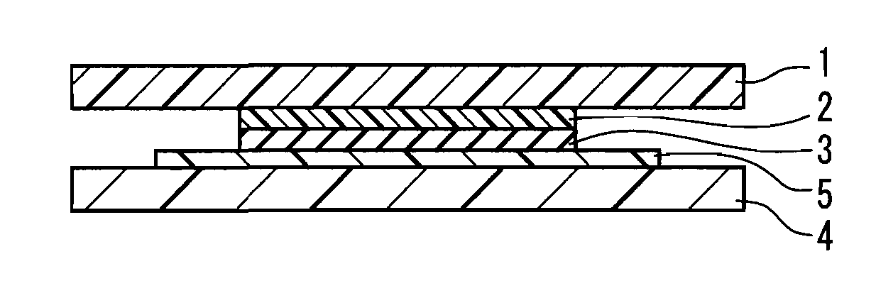
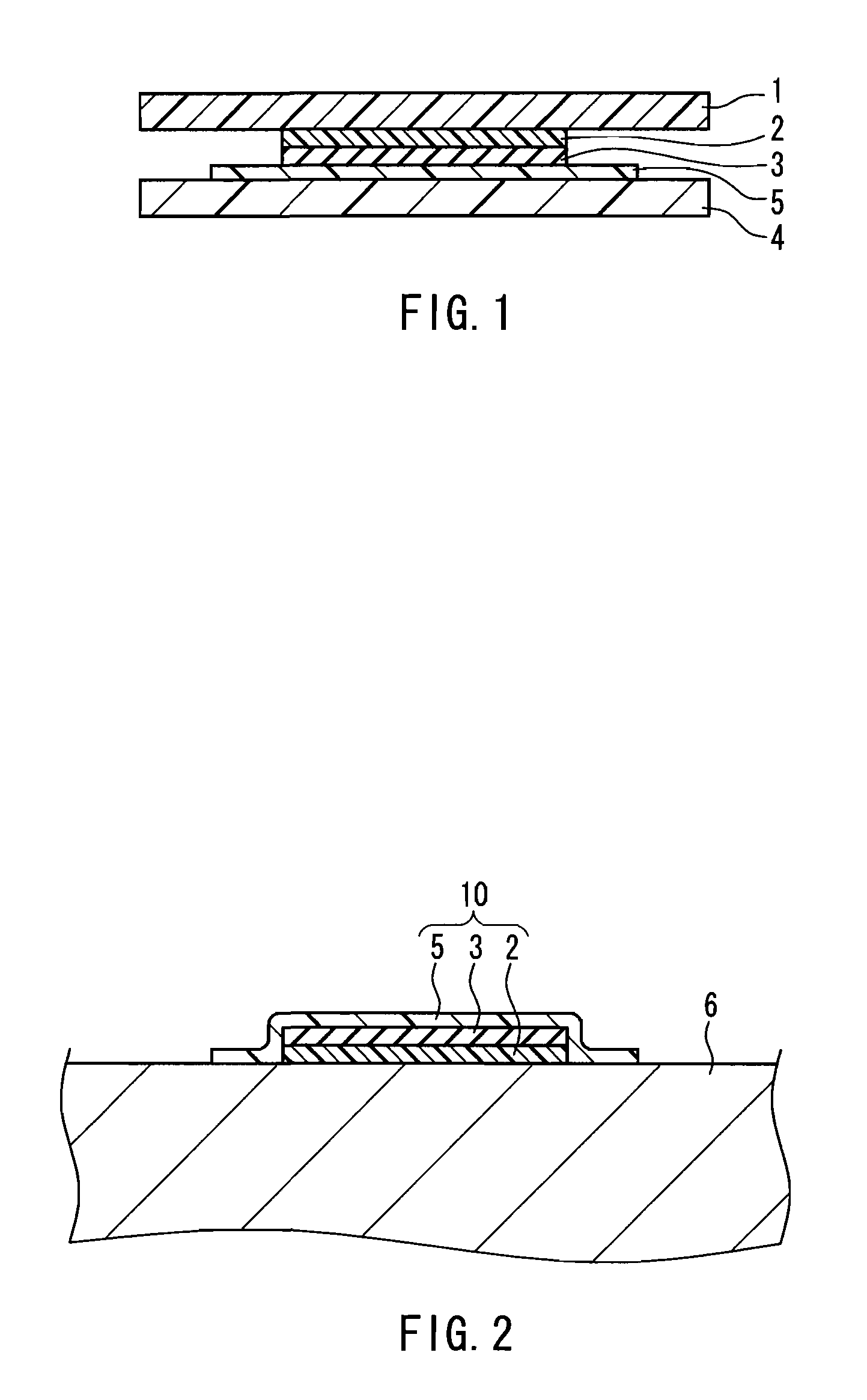
[0066]In Examples 1 to 4, the graphite sheet was sandwiched between the thermally conductive adhesive layers that were the same in type but different in size. The thermally conductive adhesive layer made of the material A (Examples 1 and 2) or B (Examples 3 and 4) was formed on a polyester film that had been subjected to a release treatment with fluorine, and was laminated with the graphite sheet. Then, the thermally conductive adhesive layer made of the material A (Examples 1 and 2) or B (Examples 3 and 4) with a thickness of 0.25 mm was disposed on the graphite sheet. Specifically, referring to FIGS. 4A and 4B, the thermally conductive adhesive layer 2 was formed on the polyester film 1. The graphite sheet 3 having the same size as the thermally conductive adhesive layer 2 was aligned with and laminated on the thermally conductive adhesive layer 2. Moreover, the thermally conductive adhesive layer 5 was formed on a polyester film that had been subjected to a release treatment with...

examples 5 and 6

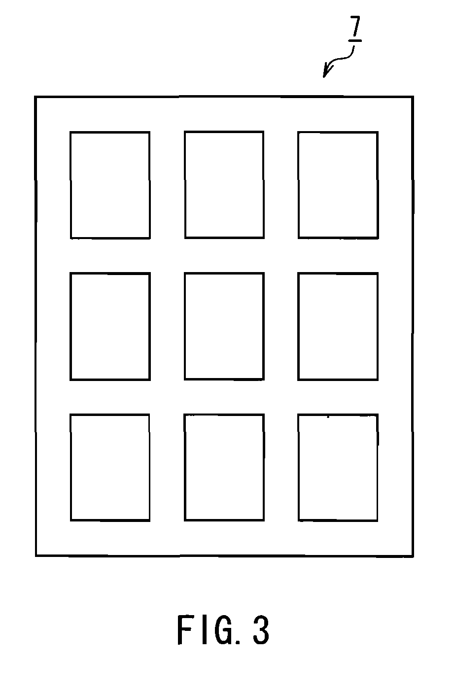
[0077]In Examples 5 and 6, the graphite sheet was sandwiched between the thermally conductive adhesive layers that were different in both type and size. The thermally conductive adhesive material D was applied to the graphite sheet by knife coating, air-dried for 30 minutes, and hardened at 120° C. for 10 minutes. The resultant adhesive layer had a thickness of 50 μm. Then, a fluorine release film was attached to the adhesive surface of the adhesive layer. This was die-cut from the graphite sheet side with a punching die 7 shown in FIG. 3 by using the polyester film (i.e., the fluorine release film) on the adhesive layer as a release liner. Subsequently, burrs were removed. FIGS. 4A and 4B are a plan view and a cross-sectional view of the laminated sheet thus produced, respectively. In FIGS. 4A and 4B, reference numeral 1 denotes the fluorine-treated polyester film, 2 denotes the thermally conductive adhesive layer made of the material D, and 3 denotes the graphite sheet.

[0078]The t...


PUM

PropertyMeasurementUnit
thermal conductivityaaaaaaaaaa
adhesive strengthaaaaaaaaaa
thermal conductivityaaaaaaaaaa

Abstract

A thermal diffusion sheet of the present invention includes a graphite sheet and thermally conductive adhesive layers attached to both principal surfaces of the graphite sheet. The thermally conductive adhesive layer on a first surface is substantially the same in size as the graphite sheet. The thermally conductive adhesive layer on a second surface is relatively larger in size than the thermally conductive adhesive layer on the first surface, and the entire periphery of the thermally conductive adhesive layer on the second surface lies outside the graphite sheet. The adhesive strength of the thermally conductive adhesive layers on the first and second surfaces after exposure to 40° C. for 168 hours is reduced by no more than 20% relative to the initial adhesive strength. Ahardened material of a polymer component of the thermally conductive adhesive layers on the first and second surfaces has a thermal conductivity of 0.6 W/m·K or more. With this configuration, the thermal diffusion sheet has a structure in which the graphite sheet is sealed by attaching the thermally conductive adhesive layer that is larger than the graphite sheet and has a good thermal conductivity in the plane direction to a radiator plate, and can transfer heat to the radiator plate reliably at a low cost.

Description

BACKGROUND OF THE INVENTION[0001]1. Field of the Invention[0002]The present invention relates to a thermal diffusion sheet that diffuses heat from a thermally conductive component of a semiconductor component such as a light emitting diode (LED) and a heat generating portion of an image display apparatus such a plasma display (PDP) or a liquid crystal display (LCD), and a method for mounting the thermal diffusion sheet.[0003]2. Description of Related Art[0004]A semiconductor such as a computer (CPU), a transistor, or a light emitting diode (LED), a power module, a plasma display (PDP), a liquid crystal display (LCD), etc. generate heat during operation and the performance can decrease due to the heat. For this reason, electronic components that generate heat are provided with a heat dissipating element. A graphite sheet is known to have an excellent thermal conductivity in the plane direction, and thus has been used as a heat dissipating material by utilizing its thermal conductivit...

Claims


Application Information

Patent Timeline
Patent Type & Authority Applications(United States)
IPC IPC(8): B32B37/14B32B7/12
CPCB32B7/12B32B9/00H01L23/373H01L23/3735H01L23/433Y10T428/24752H01L2924/0002H01L33/641Y10T156/10Y10T156/1089H01L2924/00B32B9/007B32B9/045B32B27/08B32B27/20B32B27/283B32B27/308B32B27/32B32B3/04B32B3/08B32B2307/206B32B2307/302B32B2307/306B32B2457/00B32B2457/202B32B2457/204
Inventor HATTORI, MASAKAZUFUKUI, YOSHIHIROFUNAHASHI, HAJIMENATSUME, EIICHI
Owner FUJI POLYMER INDUSTRIES CO LTD
Why Eureka
Try Eureka