

Solid-state lighting device
- Summary
- Abstract
- Description
- Claims
- Application Information
AI Technical Summary
Benefits of technology
Problems solved by technology
Method used
Image

Examples
example 1
[0085]An example lighting device according to one embodiment of the present invention provides light of predetermined correlated colour temperature (CCT) or predetermined intensity or both. This example lighting device does not employ a sophisticated CCT or intensity control system with optical or thermal feedback sensors. It is noted that lighting device according to other embodiments of the present invention may include corresponding control systems.
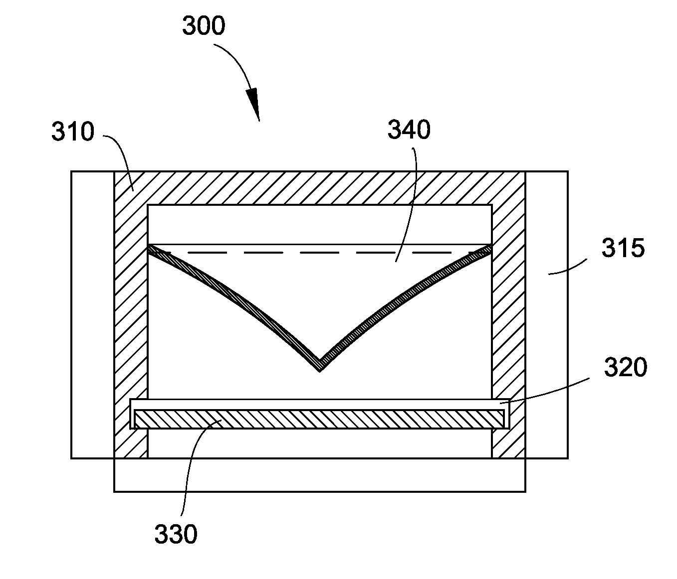
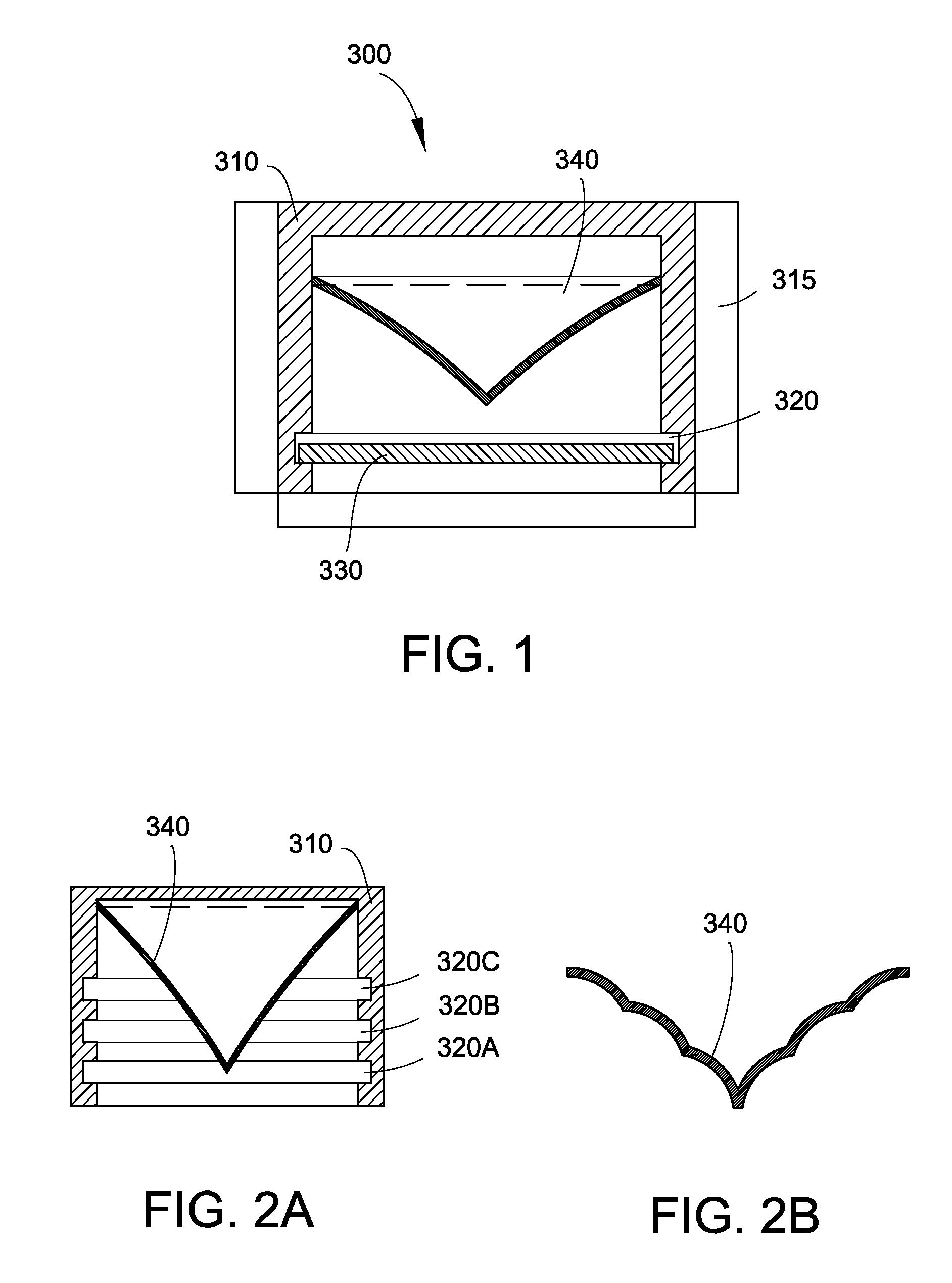
[0086]Referring again to FIG. 1, in one embodiment, lighting device includes a housing comprising heat spreading chassis 310 thermally connected to exterior cooling fins 315 or other exterior surface-increasing elements to improve air convection. The chassis can be configured in various forms, including linear, curved, or curvilinear and may have cylindrical or prismatic inside surfaces and it can have an elliptical or regular or irregular polygonal shaped cross sections. It is noted that polygonal and elliptical cross sections can imp...
example 2
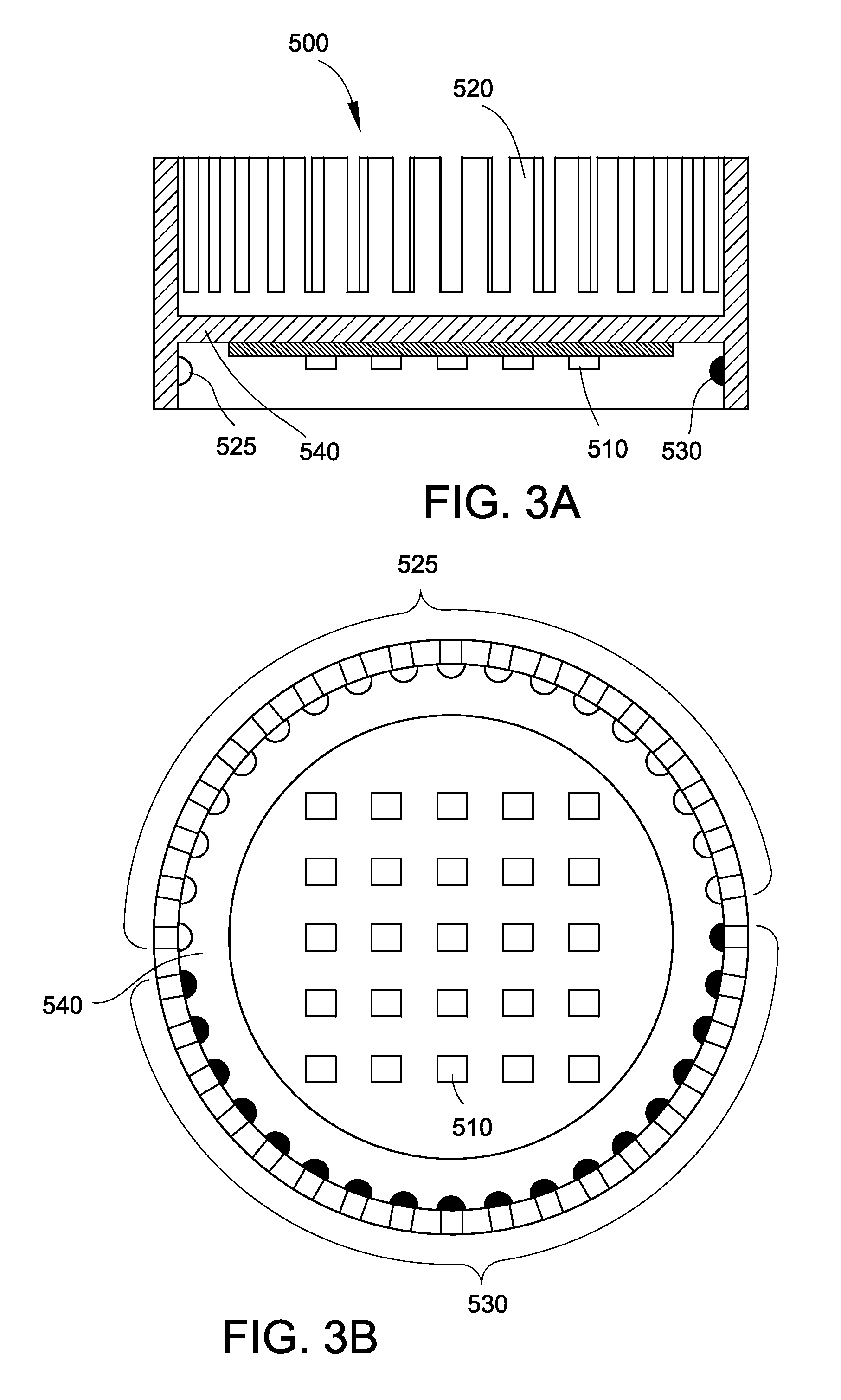
[0096]FIG. 3 schematically illustrates white LEEs positioned on a heat sink in the middle or on an inside surface of a rear wall of the lighting device. A heat pipe may be used to transfer the excess heat produced by these LEEs towards the outside of the lighting device and further on to, for example, exterior heat dissipating fins. The blue and green LEEs are located around the inner curved surface of the housing. They may be mounted on resiliently biased flexible substrates. The substrates are thermally well conducting. The number of white LEEs may be significantly higher, for example, five to ten times, than the number of blue or green LEEs.
[0097]According to another embodiment of the present invention, the lighting device comprises a combination of high power LEEs and smaller low power LEEs. The lighting device also comprises an AC-DC power converter. This may increase heat load over simpler purely rectifier circuit based embodiments but can greatly reduce thermal stress and may...
example 3
[0099]According to yet another embodiment of the present invention and as illustrated in FIG. 13, a lighting device can comprise a ring of blue or white LEEs 1410, with beam conditioning components 1420 and 1430 which can comprise reflective surfaces with predetermined surface textures. Optionally, for example, red and green LEEs 1440 can be used to control the CCT of the emitted light. The reflector 1450 can be optionally coated with a photoluminescent material such as certain phosphors, for example. Optional optical sensor 1460 can be operatively connected to an optional control system and can be used to sense light and provide certain information about the light for processing to the control system. Optical elements 1470 can be used to achieve desired beam collimation and illumination.
[0100]FIG. 14 illustrates a lighting device similar to that as illustrated in FIG. 13, further including an optional refractive element 1480 positioned below the red and green LEEs. The optical comp...
PUM
| Property | Measurement | Unit |
|---|---|---|
| Flexibility | aaaaa | aaaaa |
| Surface area | aaaaa | aaaaa |
Abstract
Description
Claims
Application Information