Control device and control system for electric rotating machine

a control device and control system technology, applied in the direction of dynamo-electric converter control, motor/generator/converter stopper, dynamo-electric gear control, etc., can solve the problems of undesirably the probability of considerable etc., to achieve the effect of lowering the controllability of the machine, reducing the probability of fluctuation of the control voltage of the circui

Active Publication Date: 2010-06-03
DENSO CORP
View PDF16 Cites 19 Cited by
  • Summary
  • Abstract
  • Description
  • Claims
  • Application Information

AI Technical Summary

Benefits of technology

[0014]According to a first aspect of this invention, the object is achieved by the provision of a control device for controlling a multi-phase electric rotating machine by controlling a power inverter circuit to output a controlled voltage of a multi-phase current to the machine. The control device comprises a phase determining unit, a norm calculating unit, a norm correcting unit, and a torque feed-back control unit. The phase determining unit determines a phase of the controlled voltage at a controlled phase to control an operating torque, generated in the machine from the controlled voltage set at the controlled phase, to a target torque under a torque feed-back control. The norm calculating unit calculates an instructed vector norm of the controlled voltage while using a parameter indicating a characteristic of the machine to control a current, flowing through the machine in response to the controlled voltage set at the instructed vector norm and the controlled phase, to an instructed current corresponding to the target torque under an open-loop control. The norm correcting unit corrects the instructed vector norm of the norm calculating unit to an adjusted vector norm to control an operating current, flowing through the machine in response to the controlled voltage set at the adjusted vector norm and the controlled phase, to the instructed current under a feed-back control. The torque feed-back control unit controls the machine to generate the target torque in response to the controlled voltage, set at the controlled phase of the phase determining unit and the adjusted vector norm of the norm correcting unit, under the torque feed-back control.
[0015]With this structure of the control device, assuming that the device has no correcting unit, the controlled voltage is set at the controlled phase and the instructed vector norm according to the target torque, the operating torque actually generated in the electric rotating machine and the parameter, and this controlled voltage is applied from the power inverter circuit to the machine to generate the target torque from the controlled voltage in the machine. That is, the control device performs a torque feed-back control to control the torque of the machine to the target torque. However, when an actual value of the parameter is differentiated from a designed value, the operating current, flowing through the machine in response to the controlled voltage, is shifted from the instructed current corresponding to the target torque. In this case, when the control device changes the torque feed-back control to a current feed-back control, in which the phase of the controlled voltage is adjusted under the pulse width modulation (PWM) control such that the operating current is controlled to the instructed current, in response to a change in the target torque, there is a high probability that the control voltage of the circuit is considerably fluctuated. Therefore, the controllability in the control of the machine is undesirably lowered.
[0016]In contrast, in this invention, the correcting unit corrects the instructed vector norm to a adjusted vector norm according to the operating and instructed currents such that the operating current is controlled to the instructed current under the feed-back control. Therefore, during the torque feed-back control, the operating current is controlled to the instructed current. In this case, when the control device changes the torque feed-back control to the current feed-back control, the control voltage of the circuit is smoothly changed without any rapid change.
[0017]Accordingly, the control device can control the torque, generated from the controlled voltage in the machine, at a high controllability while adjusting the phase of the controlled voltage.
[0018]According to the second aspect of this invention, the object is achieved by the provision of a control system comprising the control device and the power inverter circuit controlled by the control device.
[0019]Accordingly, the control system can control the torque, generated from the controlled voltage in the machine, at a high controllability while adjusting the phase of the controlled voltage.

Problems solved by technology

In this case, when the control device changes the torque feed-back control to a current feed-back control, in which the phase of the controlled voltage is adjusted under the pulse width modulation (PWM) control such that the operating current is controlled to the instructed current, in response to a change in the target torque, there is a high probability that the control voltage of the circuit is considerably fluctuated.
Therefore, the controllability in the control of the machine is undesirably lowered.

Method used


Image

  • Control device and control system for electric rotating machine
  • Control device and control system for electric rotating machine
  • Control device and control system for electric rotating machine

Examples


first embodiment

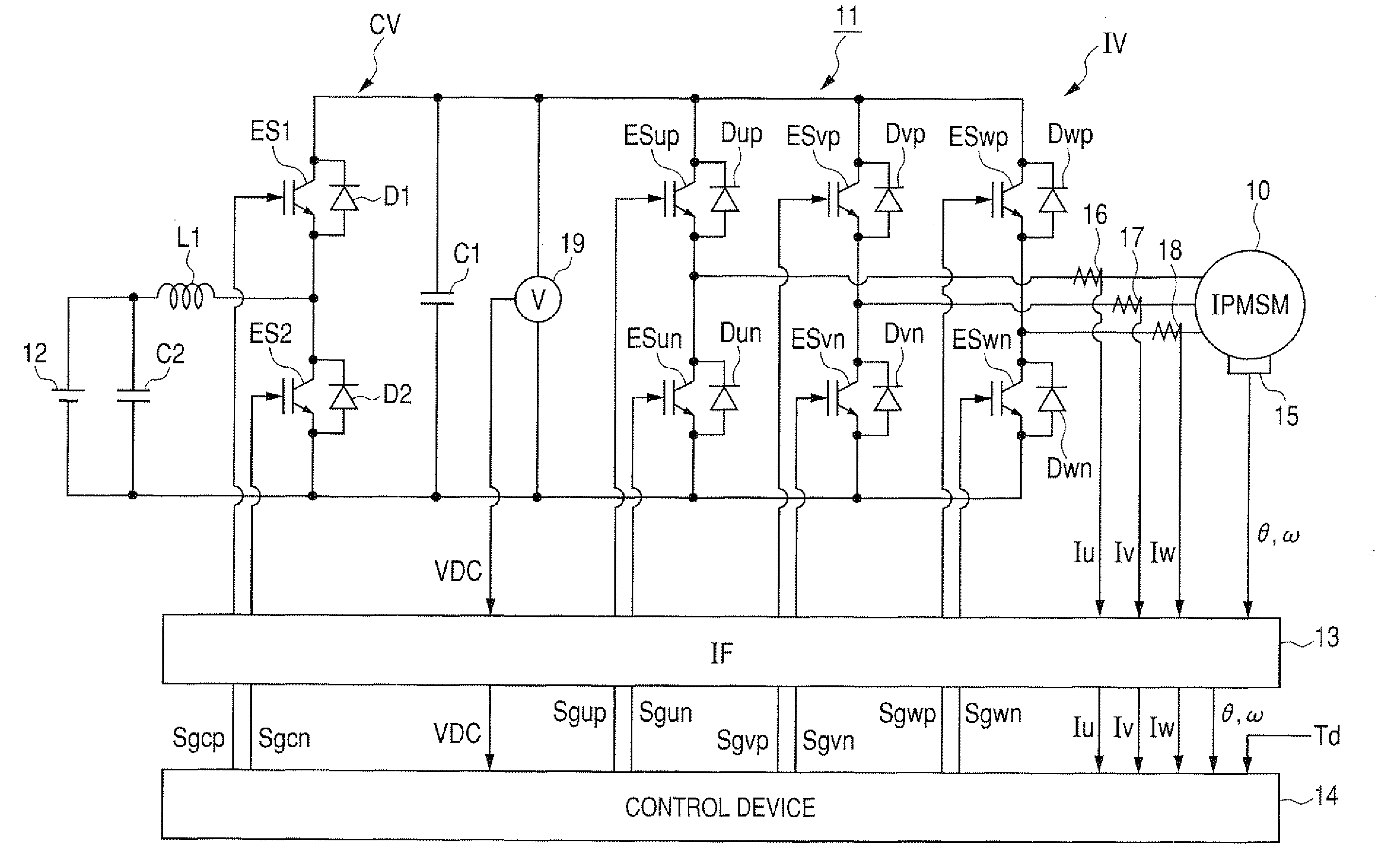
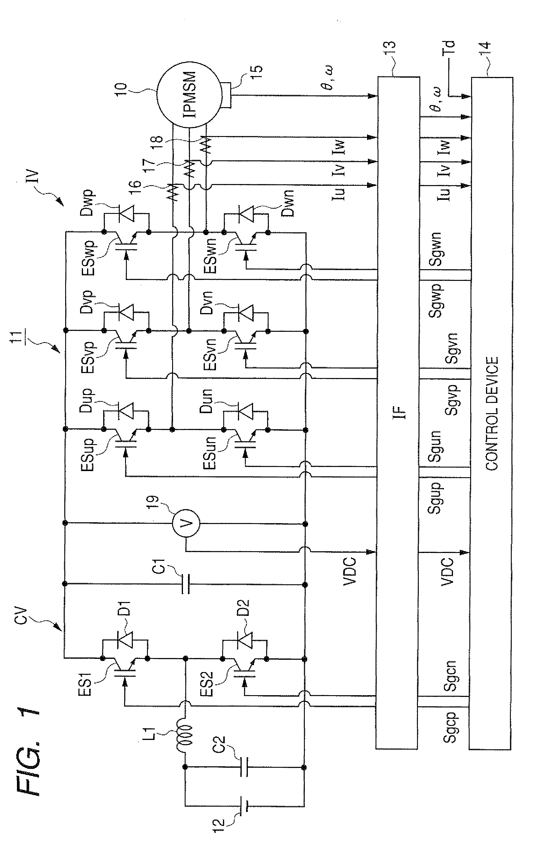
[0036]FIG. 1 is a view showing the structure of a control system for a motor generator according to the first embodiment.

[0037]As shown in FIG. 1, electric power of a high-voltage battery 12 is supplied to a motor generator 10 through a control system 11. This power generating system including the generator 10, the system 11 and the battery 12 is, for example, mounted on a hybrid vehicle. The generator 10 represents an electric rotating machine whose feature is the presence of magnetic saliency. More specifically, the generator 10 is a three-phase interior permanent magnet synchronous motor (IPMSM). This motor has a rotor, permanent magnets having salient poles and being disposed around a shaft of the rotor so as to be protruded from the shaft, a stator surrounding the rotor, and three windings (i.e., a u-phase winding, a v-phase winding and a w-phase winding) wound on the stator.

[0038]The control system 11 has a boost converter CV for boosting the voltage (e.g., 288V) of the batter...

second embodiment

[0117]In the first embodiment, even when the unit 46 switches the select ion from the torque feed-back control of the section 30 to the current feed-back control of the section 20, fluctuations of the controlled voltage Vc can be reduced. However, when the unit 46 switches the selection from the current feed-back control of the section 30 to the torque feed-back control, the norm correction Vncor becomes zero due to the gain of the block B18 initialized to zero. Therefore, fluctuations of the controlled voltage Vc are sometimes caused.

[0118]In the second embodiment, the unit 36b is configured such that the norm correction Vncor is appropriately set, just after the switching to the torque feed-back control, to correct the instructed vector norm Vn1 of the unit 36a by the correction Vncor.

[0119]FIG. 10 is a block diagram of the unit 36b according to the second embodiment. All blocks of the unit 36b are operated every unit time in response to a timing signal (not shown).

[0120]As shown ...


PUM


Abstract

A control device has a unit for determining a controlled phase of a controlled voltage outputted from an inverter to a generator according to a difference between a target torque and an estimated torque of the generator, a unit for calculating an instructed vector norm of the controlled voltage from the target torque, an electrical angular speed of the generator and parameters indicating characteristics of the generator, a unit for correcting the instructed norm to an adjusted vector norm such that a phase of current flowing through the generator in response to the controlled voltage set at the controlled phase and the adjusted norm is controlled to a phase of an instructed current determined from the target torque, and a unit for controlling the generator by controlling the inverter to output the controlled voltage set at the controlled phase and the adjusted norm to the generator.

Description

CROSS-REFERENCE TO RELATED APPLICATION[0001]This application is based upon and claims the benefit of priority of the prior Japanese Patent Application 2008-303627 filed on Nov. 28, 2008, so that the contents of which are incorporated herein by reference.BACKGROUND OF THE INVENTION[0002]1. Field of the Invention[0003]The present invention relates to a control device which controls a torque generated in an electric rotating machine by controlling a voltage outputted from a power inverter circuit to the machine, and also relates to a control system having the control device and the power inverter circuit.[0004]2. Description of Related Art[0005]A control device for a three-phase motor has been used. For example, to control three phase currents, actually flowing through respective phase windings of the motor, to instructed values under the feed-back control, this device performs a pulse width modulation (PWM) control for the motor. In this PWM control, instructed values of phase voltage...

Claims


Application Information

Patent Timeline
Patent Type & Authority Applications(United States)
IPC IPC(8): H02P6/08H02P21/00H02P21/14H02P21/18H02P21/22H02P21/24H02P23/14H02P27/04H02P27/08
CPCH02P21/0021H02P21/06H02P21/148H02P2101/45H02P2201/09H02P2205/05H02P2207/05H02P27/08H02P21/20
Inventor YAMAMOTO, TSUYOSHIMORIOKA, TATSURUMIYACHI, JUNJI
Owner DENSO CORP
Why Eureka
Try Eureka