Hole arranged photonic crystal fiber for low loss, tight fiber bending applications

a photonic crystal fiber and fiber bending technology, applied in the field of hole-assisted optical fiber devices, can solve the problems of increasing the size the complexity of the tasks involved in making and changing connections, and the storage and management of the connector cabinet, so as to improve the bend performance, reduce the radius of bending, and the effect of low loss hole-assisted

Inactive Publication Date: 2010-06-03
TYCO ELECTRONICS RAYCHEM BVBA
View PDF5 Cites 7 Cited by
  • Summary
  • Abstract
  • Description
  • Claims
  • Application Information

AI Technical Summary

Benefits of technology

[0009]Embodiments of the present invention allow a spare length of fiber to be provided at an optical coupler that can be joined using a suitable plug. This approach also enables field installing by low cost labor force. Another advantage of the present invention is to provide connections between optical fibers with a simple plug-in arrangement so that the fibers do not need to be positioned accurately in line with one another. Also the present invention enables an increase of fiber density in the rack and facilitates fiber identification
[0010]The HA-PCF is a low radius bending, low loss hole-assisted fiber able to connect the end facets of the parallel positioned fibers.
[0011]The HA-PCF for use in the butt coupler may be a hole-assisted fiber comprising a core glass region and a cladding glass region, wherein the cladding glass region includes multiple holes spaced apart from each other to surround the core glass region. In accordance with an aspect of the present invention, cladding region contains a plurality of holes surrounding and distanced from the core. These holes are preferably located symmetrically around the core and extend longitudinally along the length of fiber. The holes may be two D-shaped holes or truncated D-shaped holes arranged symmetrically around the care. In other embodiments, the holes comprise more hole structures arranged symmetrically around the core in a ring. The holes may be arranged having an inner edges defined by arc, e.g. equal arcs of a circle and extending outwards radially. Between the arcs circular holes may be provided called capilliaries. According to the present invention, any number of holes may surround core, preferably three or more.
[0012]In embodiments of the present invention a large amount of the cladding as viewed around at least one circle within the cladding centered on the core comprises, e.g. more than 60%, more than 70%, more than 80% or more than 90% or more than 95% made of the holes. The position of the circle should be chosen so that the amount of material of the cladding which is holes cut by the circle is a maximum. The fiber has the advantage of improved bend performance due to the presence of the holes.
[0013]The holes in any of the embodiments of the present invention can be filled with a gas or liquid having an index of refraction less than that of the cladding glass. The holes may be arranged as arcs of a circle around the core region. Between the arcs smaller circular holes may be arranged, termed capillaries.
[0014]The above summary of the present invention is not to be exhaustive nor to describe each illustrated embodiment or every implementation of the present invention. The figures and the detailed description which follow show embodiments of the present invention in more detail.

Problems solved by technology

The spare length of fiber required because of the in-line splicing configurations used until now, results in storage and management problems, increasing the size of the connector cabinets and the complexity of the tasks involved in making and changing connections.

Method used


Image

  • Hole arranged photonic crystal fiber for low loss, tight fiber bending applications
  • Hole arranged photonic crystal fiber for low loss, tight fiber bending applications
  • Hole arranged photonic crystal fiber for low loss, tight fiber bending applications

Examples


embodiment 1

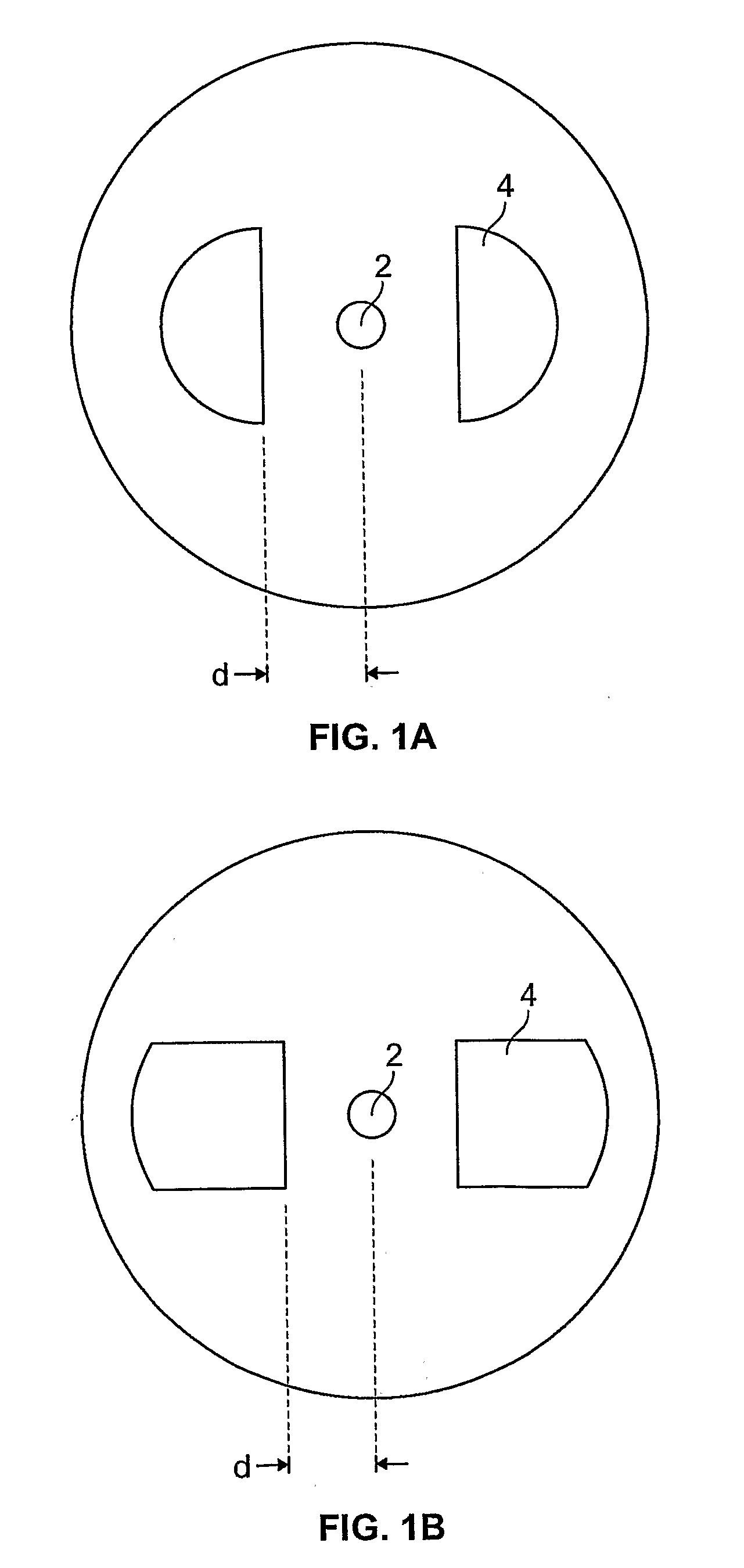
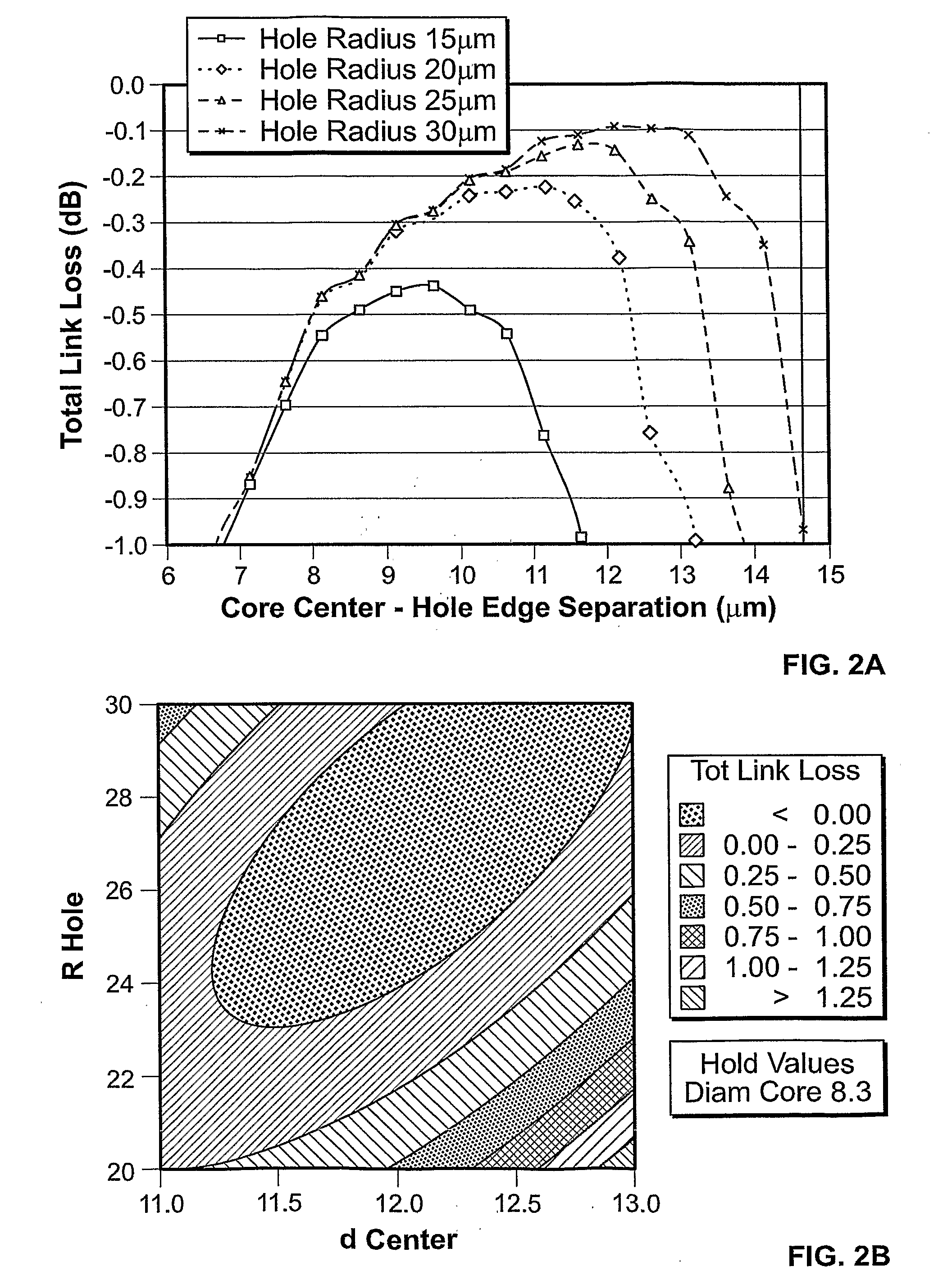
[0032]For example, FIGS. 1a and 1b show a doped core 2, with dual D hole shaped holes 4 in the cladding to form a pcf fiber that is tightly bendable in one plane (Embodiment I), e.g. to a radius of 5 mm. Tables 1 and 2 give the simulation results on this fiber. Table 1 shows dedicated settings of d (spacing between core center and the hole edge), R hole (the holes are half circles of radius R), radius of the core and core doping. The doping may be Ge and the cladding may be silica. Values of total link loss of less than 0.7 dB more preferably less than 0.6 dB, most preferably less than 0.5 dB are considered to be good at 5 mm radius bend through 180°, i.e. within the scope of the present invention. As these are loss values they may also be given a negative value in which case a preferred loss should be a lower than the absolute value of these losses. FIG. 1a shows two D-shaped holes in the cladding 4, arranged symmetrically about a core 2 with the flat sides of the “D” facing each o...

embodiment 2

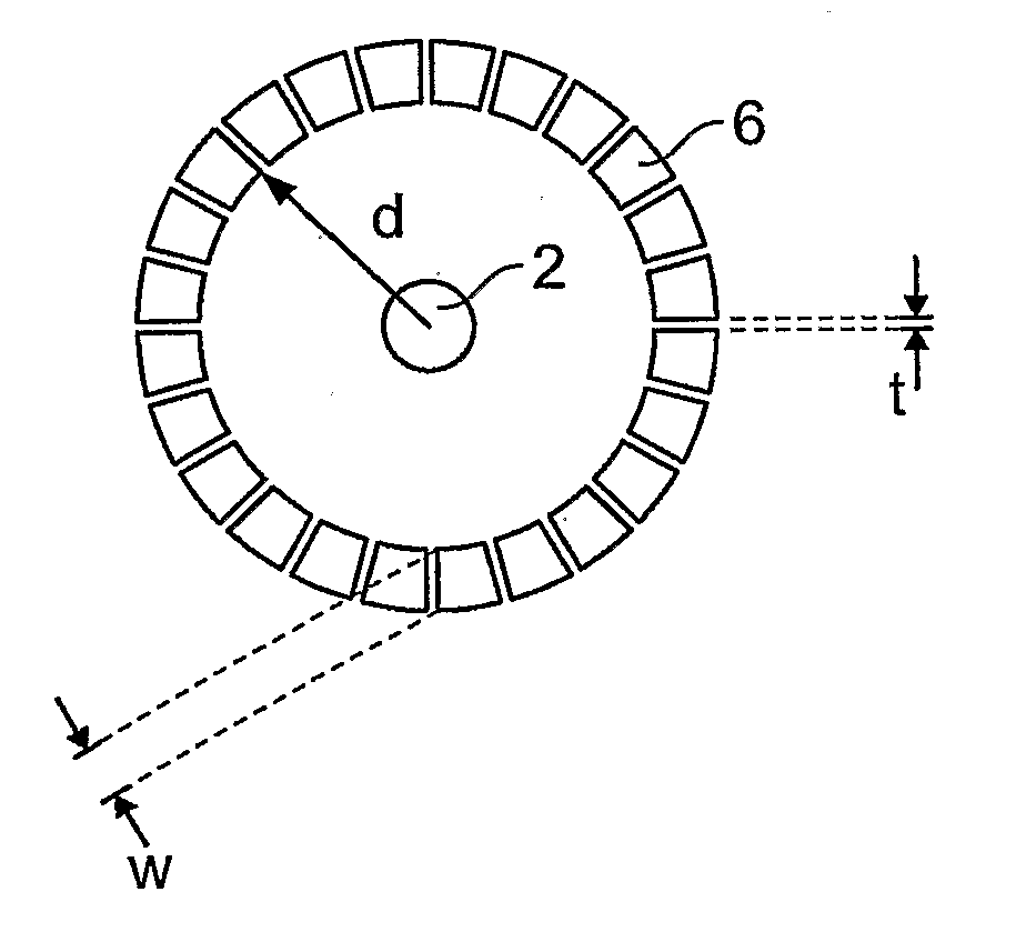
[0038]FIGS. 3A and B show embodiments in accordance with the present invention, including a ring of closely packed holes 6 arranged concentrically around a core 2. The holes 6 may be approximately square or oblong or trapezoidal (FIG. 3A) or circular or oval or egg-shaped (FIG. 3B), for example. FIG. 3B shows a manufactured sample of hole assisted fiber. Variations in hole shape and size do not affect the overall performance of the fiber significantly provided the hole to cladding ratio around a circle is not significantly affected. As shown in these embodiments a large amount of the glass or other cladding material in one circle within the cladding and centered on the core comprises the holes, e.g. more than 60%, more than 70%, more than 80% or more than 90% or more than 95% is holes.

TABLE 3widthinner cladouterTotStdOrderRunOrderPtTypeBlocksd corearmsradiusholderlink11118.611630.18522118.631280.3653311831630.28144118.611680.1855118.631280.36566118.631630.2787711831680.1728811811680...


PUM


Abstract

A microstructured fiber or photonic crystal fiber is described having a doped solid core region and a cladding region, holes being provided in the cladding region, the fiber having a low hybrid splice loss to conventional fiber as well as being able to be tightly bent due to the microstructured cladding. The cladding region can contain a plurality of holes surrounding and distanced from the core. These holes are preferably located symmetrically around the core and extend longitudinally along the length of fiber. The holes may be two or more D-shaped holes or truncated D-shaped holes arranged symmetrically around the care. In other embodiments, the holes comprise hole structures arranged symmetrically around the core in a ring. The holes may be arranged having the inner side facing the core formed from arcs of a circle, e.g. equal arcs of a circle. Between the arcs circular holes may be provided called capillaries, i.e. smaller holes. According to the present invention, any number of holes may surround the core, preferably three or more. The fiber has low loss at small bending radii.

Description

FIELD OF THE INVENTION[0001]The present invention is directed to a hole-assisted optical fiber device and methods of making and using the same. The present invention also relates to optical devices such as butt couplers for coupling light between ends of at least two optical fibers and methods of making the same.TECHNICAL BACKGROUND[0002]Optical fibers, conventionally have glass-based filaments that have a core surrounded concentrically by one or more cladding layers having appropriate indices of refraction to guide light by total internal reflection. The outer cladding layer likewise is typically covered by an external layer. The optical fiber can be designed to be a single mode fiber or a multi-mode fiber.[0003]Fiber designs have been proposed with hollow cores, sometimes referred to as “holey fibers” or “photonic crystal” fibers (PCF) or micorostructired fiber. Known methods of making microstructured or PCF fibers include using stacked arrays of cylindrical tubing or capillaries ...

Claims


Application Information

Patent Timeline
Patent Type & Authority Applications(United States)
IPC IPC(8): G02B6/24G02B6/02
CPCG02B6/02366G02B6/24G02B6/024
Inventor WATTE, JANVAN ERPS, JUERGENNASILOWSKI, TOMASZDEBAES, CHRISTOFTHIENPONT, HUGO
Owner TYCO ELECTRONICS RAYCHEM BVBA
Why Eureka
Try Eureka