Slicing device

a technology of slicing device and micro-grid, which is applied in the field of biological microgrid, can solve the problems of time-consuming and prone to contamination, different cell types are more prone to damage, and the risk of contamination, so as to avoid enzymatic dissociation and facilitate implementation

Active Publication Date: 2010-06-03
SUNDSTROM ERIK +3
View PDF6 Cites 16 Cited by
  • Summary
  • Abstract
  • Description
  • Claims
  • Application Information

AI Technical Summary

Benefits of technology

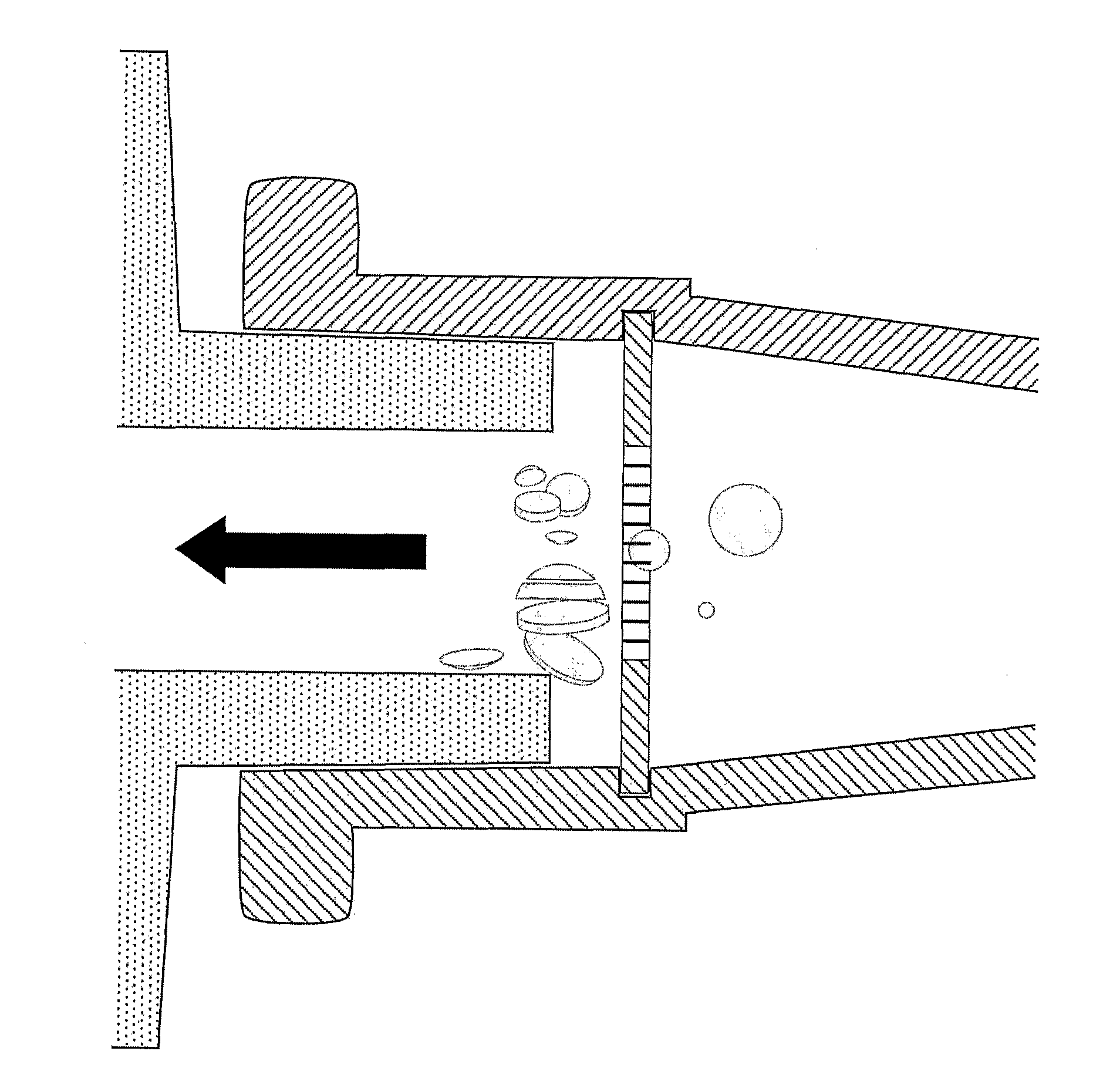
[0010]By providing a slicing device and said apparatus, it is possible to cut tissue, cell aggregates and other biological material in minute pieces of defined size, in a highly reproducible way and in large quantities. The technology can easily be implemented in fluidic systems to cut tissue or cell aggregates using automated procedures. The device described can be used for cell cultures to cut aggregates of stem cells, precursor cells, progenitor cells or mature cells by aspirating or ejecting them through the device, thereby avoiding enzymatic dissociation and the need for tryptic enzymes, as well as mechanical dissociation which is associated with considerable cell death.

Problems solved by technology

This method involves cutting the tissue with razor blades or scissors, which is very time consuming and prone to contamination.
Depending on the strength of the bonds between cells, different cell types may be more prone to damage during dissociation.
Adding enzymes for the dissociation process also introduces a risk of contamination as well as the problem that low concentrations of enzymes can remain in cells used for cell therapy.

Method used


Image

  • Slicing device
  • Slicing device
  • Slicing device

Examples


example 1

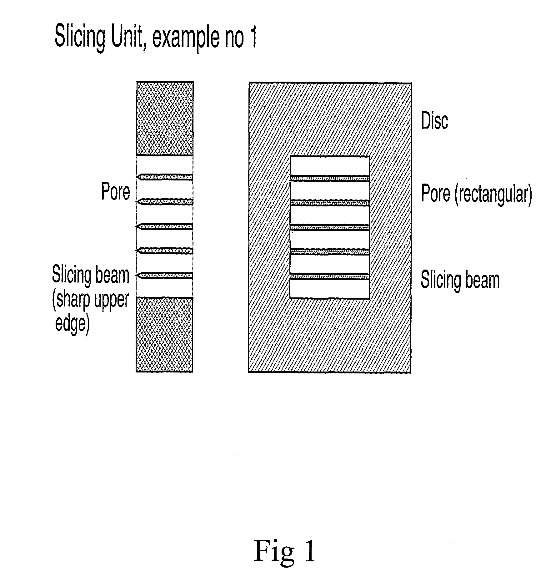
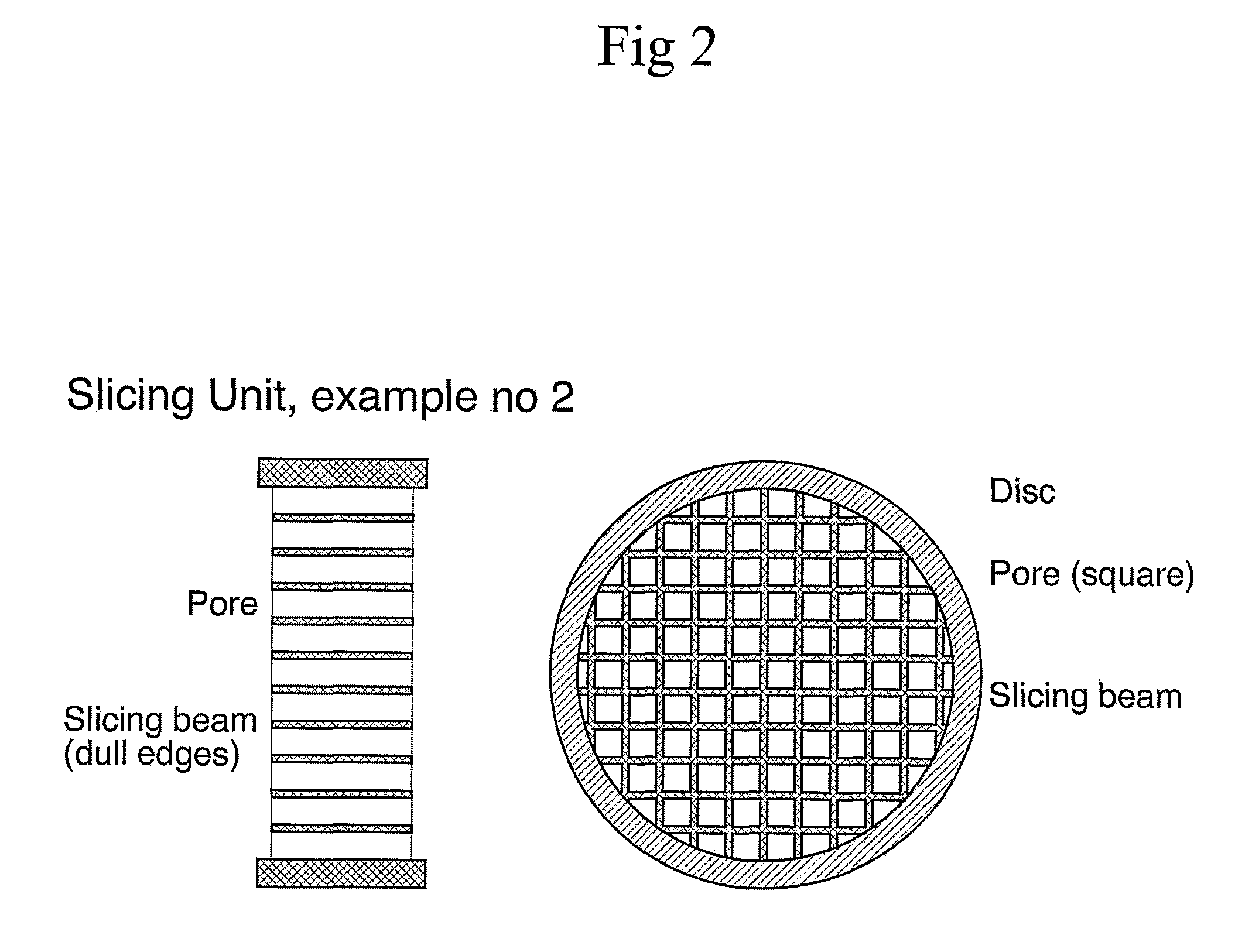
[0029]A microgrid can be manufactured by convention microfabrication technologies. The desired projected shape of the microgrid is defined my photolithography on a silicon wafer, outlining multiple microgrids on a single silicon wafer. The exposed and developed wafer is subsequently subjected to wet or dry etching to produce the desired microstructures that compose the microgrid, with the desired beam widths and lengths and corresponding distance between beams. If other pore dimensions, round holes, square grid patterns etc. are desired this is accomplished by modifying the photolithographic mask. After the etch process the individual slicing devices are commonly released from the wafer by conventional wafer dicing saw equipment.

example 2

[0030]One microgrid with a pore size of 100×500 μm and a width of the slicing beams of 30 μm is cast in a polymer cylinder with an inner diameter of 1.5 mm fitted at one end with a 15 cm long stainless steel tube, inner diameter 0.7 mm, and at the other end with an opening fitting on a standard plastic 10 ml sterile disposable syringe. By slowly aspirating and ejecting media containing free-floating cell aggregates through this device, the cell aggregates are sliced into smaller aggregates.

example 3

[0031]Two replaceable microgrids with quadratic pores, size 10 μm, beam width 2 μm, placed in series in a cylinder with luer fittings at both ends. Cell aggregates or pieces of tissue are collected in fluid in a separate container, the pressure in the container increased to force the biological material through the two microgrids, thereby creating a suspension of single cells, without the need of enzymatic dissociation.


PUM

PropertyMeasurementUnit
sizeaaaaaaaaaa
sizeaaaaaaaaaa
sizeaaaaaaaaaa

Abstract

The invention relates to a biological microglia comprising at least two pores having a size adopted to allow cells, cell aggregates, tissue or other biological material to pass through said pores, and one or several slicing beams separating said pores from each other, wherein biological material is split/sliced/cleaved into at least two parts when passing said microgrid, a slicing device, an apparatus comprising said slicing device as well as the use of said microgrid, slicing device and apparatus.

Description

FIELD OF INVENTION[0001]The invention relates to a biological microgrid comprising at least two pores having a size adopted to allow cells, cell aggregates, tissue or other biological material to pass through said pores, and one or several slicing beams separating said pores from each other, wherein biological material is split / sliced / cleaved into at least two parts when passing said microgrid, a slicing device, an apparatus comprising said slicing device as well as the use of said microgrid, slicing device and apparatus.BACKGROUND OF INVENTION[0002]Immature cells, so called stem cells, progenitor cells or precursor cells, with the potential to develop into different types of mature cells, is the most promising strategy for restoring injured tissue.[0003]Stem cells (used in this text to denominate all types of immature, multipotent cells) can be isolated from different sources. Embryonic stem cells are derived from surplus fertilized egg cells, fetal stem cells are isolated from emb...

Claims


Application Information

Patent Timeline
Patent Type & Authority Applications(United States)
IPC IPC(8): C12N5/02C12M1/00
CPCC12M45/02
Inventor SUNDSTROM, ERIKKESSON, ELISABETLAURELL, THOMASWALLMAN, LARS
Owner SUNDSTROM ERIK
Why Eureka
Try Eureka