Superelastic Alloy Structural Geometry for Ultrahigh Mechanical Damping

a technology of structural geometry and alloys, applied in the direction of woven fabrics, textiles and paper, braids, etc., can solve the problems of ineffective or even applicable conventional macro-scale damping structures, many complicated mechanical systems can malfunction or be damaged, and many complicated mechanical systems can be damaged. , to achieve the effect of more precise and reliabl

Active Publication Date: 2010-06-10
MASSACHUSETTS INST OF TECH
View PDF6 Cites 15 Cited by
  • Summary
  • Abstract
  • Description
  • Claims
  • Application Information

AI Technical Summary

Benefits of technology

[0010]With this arrangement, the mechanical structure of the invention enables ultra-high-damping performance characteristics and response times on the order of just a few milliseconds. These qualities provide a practical solution for a new generation of more precise and reliable MEMS and the growing class of nano-scale devices and systems, as well as a wide range of meso-scale and macro-scale systems.

Problems solved by technology

Indeed, without vibration suppression or mechanical isolation, many complicated mechanical systems can malfunction or be damaged, or demonstrate only suboptimal operational performance.
But for many mechanical systems, conventional macro-scale damping structures are not effective or even applicable.
Such micro-scale systems, as well as nano-scale systems, are not in general amenable to conventional damping structures.
Yet while damping and fatigue characteristics are of paramount importance for MEMS, these properties are often on opposite sides of a trade-off.
But silicon MEMS structures can fatigue through an oxidation mechanism during air exposure.
The resulting oxidation fatigue can be alleviated by vacuum packaging, but this is found to exacerbate the transmission of mechanical shock and noise to MEMS components from their use environment.
Thus, one of either structural integrity or mechanical operation performance often must be compromised in favor of the other in advanced sensing and actuating MEMS technologies.
This example demonstrates that for many mechanical systems, across a range of dimensions, mechanical damping requirements can often not be well-addressed without a required compromise in protection against environmental conditions, without limits on operational performance, precision, or reliability, or without prejudicing another consideration in the success of the system.
Conventional mechanical damping configurations have heretofore necessitated such compromises and as a result have limited the applications of mechanical systems in the meso-scale, micro-scale, and nano-scale regimes.

Method used


Image

  • Superelastic Alloy Structural Geometry for Ultrahigh Mechanical Damping
  • Superelastic Alloy Structural Geometry for Ultrahigh Mechanical Damping
  • Superelastic Alloy Structural Geometry for Ultrahigh Mechanical Damping

Examples


example i

[0076]A superelastic alloy composition of Cu 81.3 wt %-Al 13.7 wt %-Ni 5 wt %, having a melting temperature of about 1100° C., was produced in melt form and drawn into superelastic alloy fibers of varying diameters. The fibers were produced by Taylor wire hot drawing through a glass tube of Borosilicate Pyrex glass of 80.6 wt % SiO2, 12.6 wt % B2O3, 4.2 wt % Na2O, and 2.2 wt % Al2O3, having a softening temperature of about 820° C., a working temperature of about 1200° C. and an inner diameter of about 4 mm. The fibers were drawn at a temperature above the melting point in a low vacuum. Thirteen different fiber diameters were achieved ranging from about 450 microns in diameter to about 20 microns in diameter, with draw speeds ranging between about 1-4 m / s. Once drawn, the fibers were annealed at a temperature of about 850° C. in an argon atmosphere for about one hour and then quenched in cold water to impart a bamboo microstructure to the fibers. Afterwards, the glass coating on the ...

example ii

[0082]oriented single crystals of the Cu—Al—Ni alloy Cu-13.7Al-5Ni (wt %) were characterized. This alloy exhibits transformation temperatures of Ms=291 K, Mf=273 K, As=285 K and Af=303 K, corresponding to the temperatures of the martensitic phase start and finish and the austenitic phase start and finish, respectively. This alloy is in the austenitic phase (cubic) at room temperature and consequently is susceptible to stress-induced transformation to β′ martensite (monoclinic).

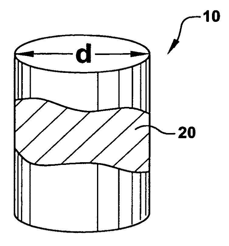
[0083]Micro- and nano-scale pillars of the alloy were produced by focused ion beam (FIB) micromachining with a FEI Dual Beam DB235 instrument. Each pillar was machined from the surface of sections cut from bulk Cu—Al—Ni single crystals. Micro-compression tests were then performed on the pillars by instrumented nano-indentation with a Hysitron Triboindenter and using a sphero-conical diamond indenter tip of 0.6 μm in radius. One example experimental micro-pillar exhibited a slightly tapered shape with a diamete...


PUM

PropertyMeasurementUnit
grain sizeaaaaaaaaaa
diameteraaaaaaaaaa
diameteraaaaaaaaaa

Abstract

A mechanical structure is provided with a crystalline superelastic alloy that is characterized by an average grain size and that is characterized by a martensitic phase transformation resulting from a mechanical stress input greater than a characteristic first critical stress. A configuration of the superelastic alloy is provided with a geometric structural feature of the alloy that has an extent that is no greater than about 200 micrometers and that is no larger than the average grain size of the alloy. This geometric feature is configured to accept a mechanical stress input.

Description

CROSS-REFERENCE TO RELATED APPLICATIONS[0001]This application claims the benefit of U.S. Provisional Application No. 61 / 134,363, filed Jul. 9, 2008, the entirety of which is hereby incorporated by reference.STATEMENT REGARDING FEDERALLY SPONSORED RESEARCH[0002]This invention was made with Government support under Contract No. W911NF-07-D-0004, awarded by the Army Research Office. The Government has certain rights in the invention.BACKGROUND OF INVENTION[0003]This invention relates generally to methods for suppressing mechanical vibration and mechanical impact shocks, and more particularly relates to materials and structures for suppressing mechanical vibration and impact shocks.[0004]The suppression of mechanical vibration noise and impact shocks by mechanical damping is a widely sought property in materials, not only as a matter of scientific interest, but also to enable new technologies. A wide range of proposed mechanical and electromechanical systems ranging in dimension from th...

Claims


Application Information

Patent Timeline
Patent Type & Authority Applications(United States)
IPC IPC(8): F16F7/12C22C5/10C22C9/04C22C9/06C22C9/01C22C30/02C22C19/03C22C14/00C22C28/00C22C22/00C22C38/00C22C38/10C22C38/08C22C38/04B32B15/02D03D15/00
CPCC22C9/00Y10T428/12424F16F1/021D04C1/06F16F7/00C22C38/34C22C38/14C22C38/12C22C38/105C22C38/08C22C38/04C22C38/02C22C28/00C22C22/00C22C20/00C22C9/05C22C9/04C22C9/01C22C5/10C22C5/04C22C5/02C22C38/58Y10T428/12479Y10T428/12306C22C19/03Y10T442/339F16F15/00C22C30/02C22C38/002
Inventor SCHUH, CHRISTOPHER A.SAN JUAN, JOSE M.CHEN, YING
Owner MASSACHUSETTS INST OF TECH
Why Eureka
Try Eureka