Supercharge Your Innovation With Domain-Expert AI Agents!

Objective lens system and optical pickup device

a technology of optical pickup and objective lens, which is applied in the direction of optical recording head, data recording, instruments, etc., can solve the problems of false detection of light intensity, unstable output of monitor light-receiving element, etc., and achieve the effect of stably performing

Inactive Publication Date: 2010-06-10
PANASONIC CORP
View PDF4 Cites 0 Cited by
  • Summary
  • Abstract
  • Description
  • Claims
  • Application Information

AI Technical Summary

Benefits of technology

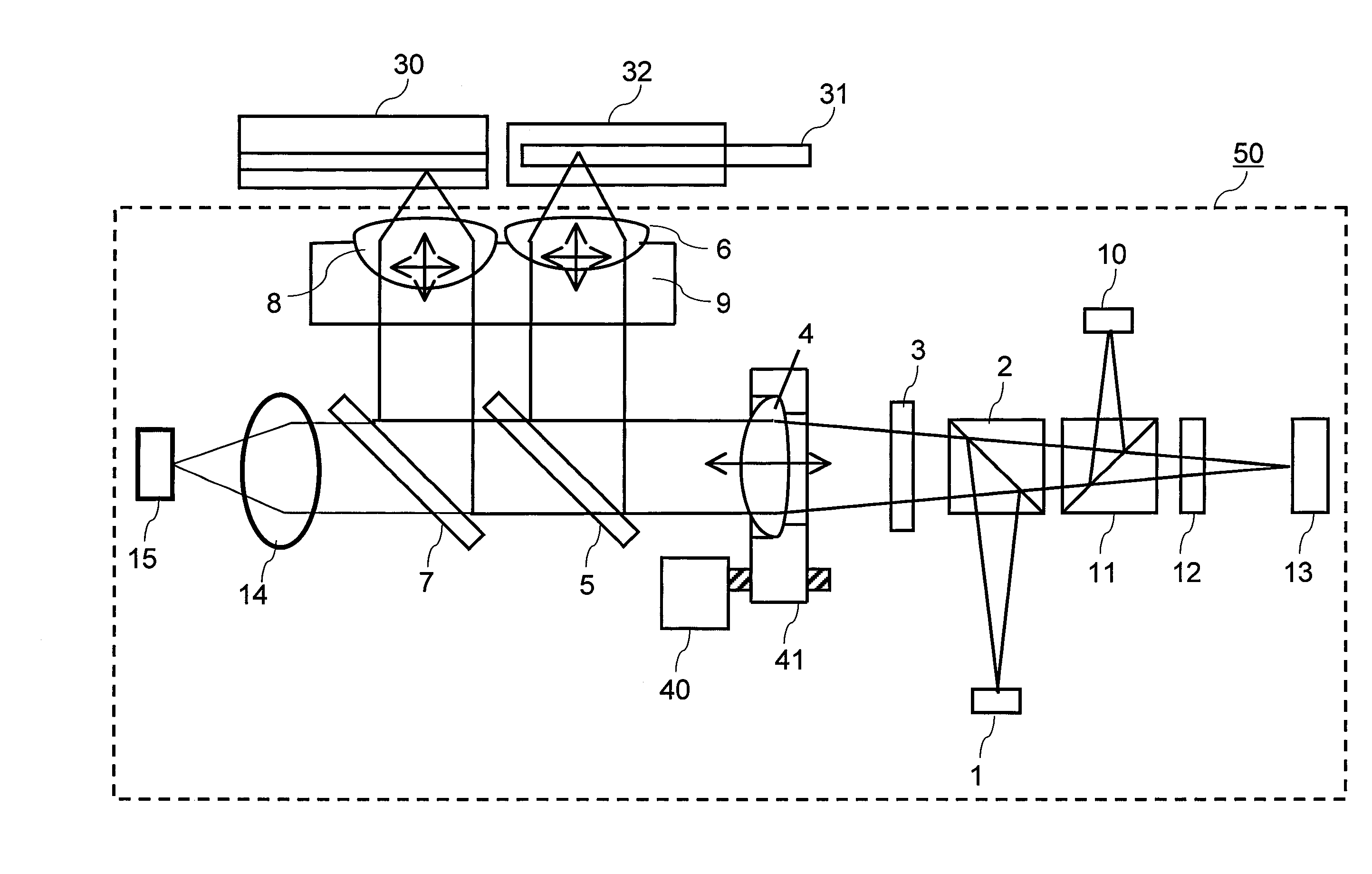
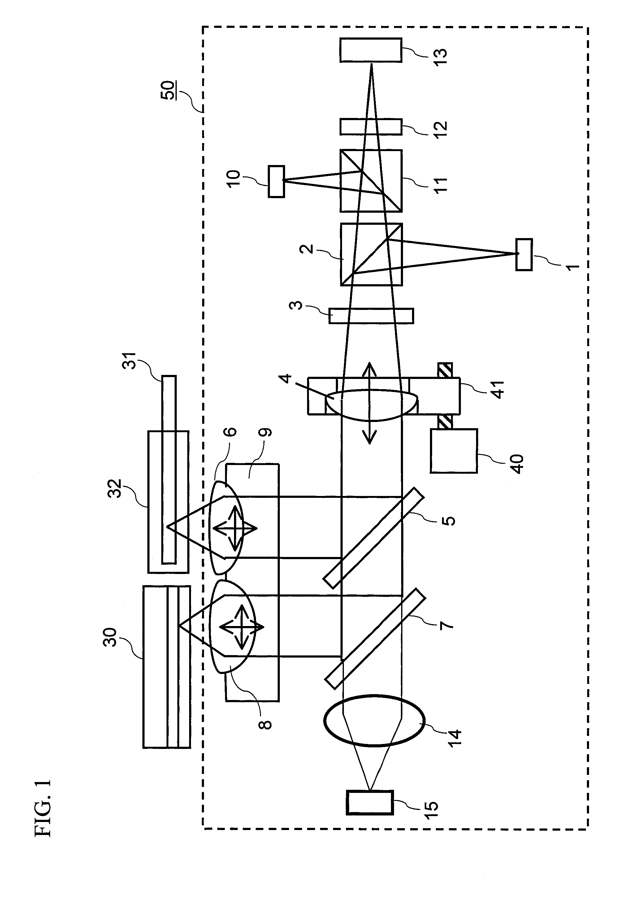
[0014]According to the present invention, in the case where an optical pickup device having a mirror for folding a light beam to be guided to an objective lens is configured, the light beam to be guided to the mirror can be converted to non-parallel light. Thereby, interference fringes caused by reflection inside the mirror can be controlled, and thus monitoring of the optical output intensity based on the light transmitted through the mirror can be performed stably.

Problems solved by technology

In this case, the light beam reflected by the inner surface of the plate-shaped mirror interfaces with the transmitted light beam, which causes a problem that the output from the monitor light-receiving element becomes unstable.
However, in the configuration where a part of the optical path is shared as described above, the lights of the different wavelengths, which have been simultaneously emitted, are synthesized to enter the monitor light-receiving element, leading to false detection of light intensity.

Method used


Image

  • Objective lens system and optical pickup device
  • Objective lens system and optical pickup device
  • Objective lens system and optical pickup device

Examples


numerical example 1

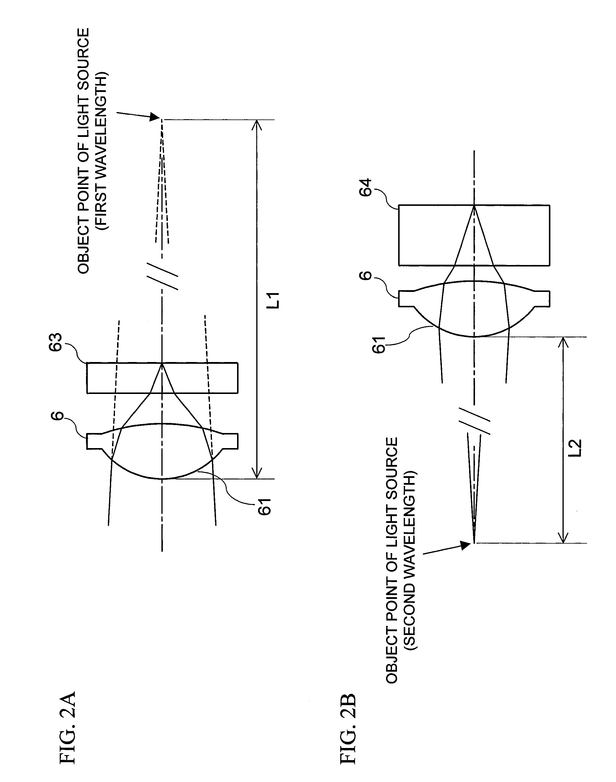
[0057]On a first surface (incident surface) of an objective lens system according to Numerical Example 1, different aspheric configurations are formed at an inner part having a height of 1.037 or below from the optical axis, and at an outer part having a height exceeding 1.037 from the optical axis. On this surface, substantially saw-tooth-shaped diffraction zones are formed in accordance with the phase function. FIG. 3 is a diagram in which phase differences (values obtained from the phase function) given by the diffraction surface of the objective lens according to Numerical Example 1 are plotted.

[0058]Table 1 shows the specification of the objective lens system according to Numerical Example 1.

TABLE 1DVDCDWavelength (nm)0.660.785Refractive indexLens1.5394811.535912Protection layer1.5781521.572031Object point distance (mm)−167130Protection layer thickness (mm)0.61.2Lens thickness (mm)1.1Focal length (mm)1.9962.008Axial wavefront aberration (mλ)5.14.1

[0059]Table 2 shows aspheric co...

numerical example 2

[0060]On a first surface (incident surface) of an objective lens system according to Numerical Example 1, different aspheric configurations are formed at an inner part having a height of 1.037 or below from the optical axis, and at an outer part having a height exceeding 1.037 from the optical axis. Also on a second surface, different aspheric configurations are formed at an inner part having a height of 0.842 or below from the optical axis, and at an outer part having a height exceeding 0.842 from the optical axis.

[0061]Table 3 shows the specification of the objective lens system according to Numerical Example 2.

TABLE 3DVDCDWavelength (nm)0.660.785Refractive indexLens1.5394811.535912Disc1.5781521.572031Object point distance (mm)−167130Disc thickness (mm)0.61.2Lens thickness (mm)1.1Focal length (mm)1.9962.009Axial wavefront aberration (mλ)3.17.3

[0062]Table 4 shows aspheric coefficients and phase function coefficients of the objective lens system according to Numerical Example 2. Not...

numerical example 3

[0063]On a first surface (incident surface) of an objective lens system according to Numerical Example 1, different aspheric configurations are formed at an inner part having a height of 1.05 or below from the optical axis, and at an outer part having a height exceeding 1.05 from the optical axis.

[0064]Table 5 shows the specification of the objective lens system according to Numerical Example 3.

TABLE 5DVDCDWavelength (nm)0.660.785Refractive indexLens1.5394811.535912Disc1.5781521.572031Optical point distance (mm)−600600Disc thickness (mm)0.641.12Lens thickness (mm)1.1Focal length (mm)1.9962.009Axial wavefront aberration (mλ)15.311.03

[0065]Table 6 shows aspheric coefficients and phase function coefficients of the objective lens system according to Numerical Example 3. Note that the diffraction order is the first order.

TABLE 6First Surfaceh ≦ 1.05RD1.3330902E+00CC1.3839376E−01A4−8.2852145E−03A6−6.3438840E−02A85.9338530E−02A10−3.7475418E−02D2−5.5223173E+01D4−4.8105469E+00D6−3.4973197E+0...


PUM

PropertyMeasurementUnit
thicknessaaaaaaaaaa
first wavelengthaaaaaaaaaa
second wavelengthaaaaaaaaaa

Abstract

Provided are an optical pickup device which is compatible with a plurality of disc standards, and can stably monitor the outputs from light sources, and an objective lens system used in the optical pickup device. An optical pickup device 50 includes a light source 1 emitting light of a first wavelength of a red band and light of a second wavelength of an infrared band; a light source 10 emitting light of a blue-violet band for BD 10; a collimating lens 4; mirrors 5, 7 each transmitting a portion of a light beam outputted from the collimating lens 4 while folding an optical path of the other portion of the light beam; objective lenses 6, 8 each converging the light beam folded by the mirrors 5, 7 on a recording layer of an optical disc; and a light-receiving element 15 detecting an intensity of the light beam transmitted through the mirrors 5, 7. The collimating lens 4 adjusts the parallelisms of the lights emitted from the light sources 1, 10, and outputs the light of the first wavelength as a converging light beam, and the light of the second wavelength as a diverging light beam.

Description

BACKGROUND OF THE INVENTION[0001]1. Field of the Invention[0002]The present invention relates to an objective lens system for performing at least one of recording, reproduction, and erasing of information on an optical storage medium, and an optical pickup device using the objective lens system.[0003]2. Description of the Background Art[0004]Optical discs have been widely used as media for recording a large amount of information. A compact disc (CD) was widespread first. Thereafter, improvement of recording density was achieved to store more information in a single information storage medium, and consequently, a digital versatile disc (DVD) was developed. Recently, a Blu-ray disc (registered trademark, BD) capable of recording information with higher density have been put to practical use.[0005]In order to realize a high-density optical disc, it is necessary to reduce the size of pits for recording. Therefore, with the improvement of recording density, the numerical aperture of an o...

Claims


Application Information

Patent Timeline
Patent Type & Authority Applications(United States)
IPC IPC(8): G11B7/135
CPCG11B7/1362G11B7/1374G11B2007/0006G11B7/13925G11B7/1376
Inventor YAMAGATA, MICHIHIROYAMASAKI, FUMITOMOKOMMA, YOSHIAKIHAYASHI, KATSUHIKO
Owner PANASONIC CORP
Features
  • R&D
  • Intellectual Property
  • Life Sciences
  • Materials
  • Tech Scout
  • Unparalleled Data Quality
  • Higher Quality Content
  • 60% Fewer Hallucinations
Learn More