Radius end mill and cutting method

a cutting method and radius end mill technology, applied in shaping cutters, metal-working machine components, manufacturing tools, etc., can solve the problems of increasing the cutting edge resistance, hardly ejecting chips from the groove easily, and missing and chipping of the cutting edge, so as to prevent the vibrating of the radius end mill, reduce the cutting resistance of the cutting device, and smooth the surface of the material

Inactive Publication Date: 2010-06-10
MITSUBISHI MATERIALS CORP
View PDF6 Cites 24 Cited by
  • Summary
  • Abstract
  • Description
  • Claims
  • Application Information

AI Technical Summary

Benefits of technology

[0022]With regard to the cutting method as described above, the depth of cutting in the axial direction with respect to the object is less than or equal to the curvature radius R of the corner cutting edge. Thus, when the material is cut using the radius end mill as described above, the material is cut by the bottom cutting edge and the corner cutting edge, and the peripheral cutting edge hardly contact the material. Therefore, the cutting resistance of the cutting device can be reduced. As a result, it is possible to prevent the radius end mill from vibrating, and it is possible to make the surface of the material smooth.
[0023]According to the present invention, when the pocket or the like is formed in the material, even if a multi-angle part and an outline of a pocket are cut, it is possible to perform the high feed-speed cutting to improve the cutting efficiency of the material. Further, it is possible to cut the surface of the material to be smooth. Furthermore, it is possible to produce the radius end mill inexpensively. In addition, the radius end mill can be re-ground for long-term use.

Problems solved by technology

Further, the cutting resistance acting on the cutting edge is increased, and thereby the lacking and chipping of the cutting edge may be happened.
Furthermore, if the chips become large, the chips are hardly ejected from the groove easily.
Therefore, the cutting resistance is increased depending upon blocking of the chips within the ejection groove, and the surface of the material to be cut is damaged by the chips.
Therefore, there is a problem that the smoothness of the surface of the material to be cut deteriorates.
Thus, the vibration of the end mill is caused by an increase of the cutting resistance.
In order to prevent the end mill from vibrating, it is necessary to reduce the forward cutting speed of the end mill Therefore, there is a problem that the cutting efficiency of the material deteriorates.
Therefore, there is a problem that the cutting efficiency of the material deteriorates.
Thus, the shape of the cutting edges is extremely complicated.
Therefore, there is a problem that the manufacturing cost of the radius end mill becomes to be expensive.
Therefore, the life span of the radius end mill is short, and the term of the replacement cycle is short.
As a result, there is a problem that the operating cost becomes expensive.

Method used


Image

  • Radius end mill and cutting method
  • Radius end mill and cutting method
  • Radius end mill and cutting method

Examples


Embodiment Construction

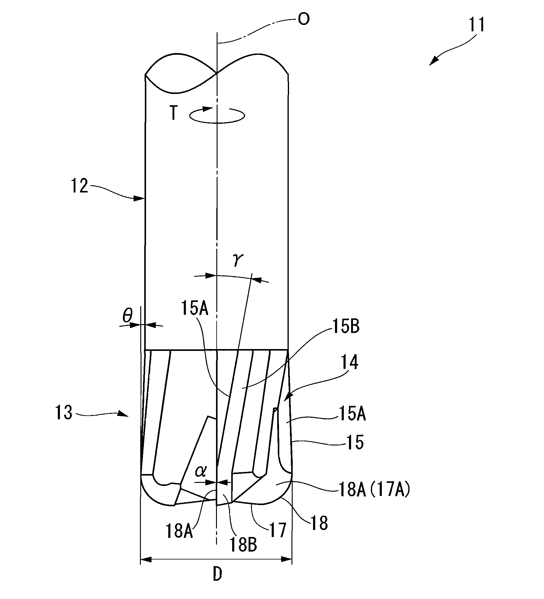
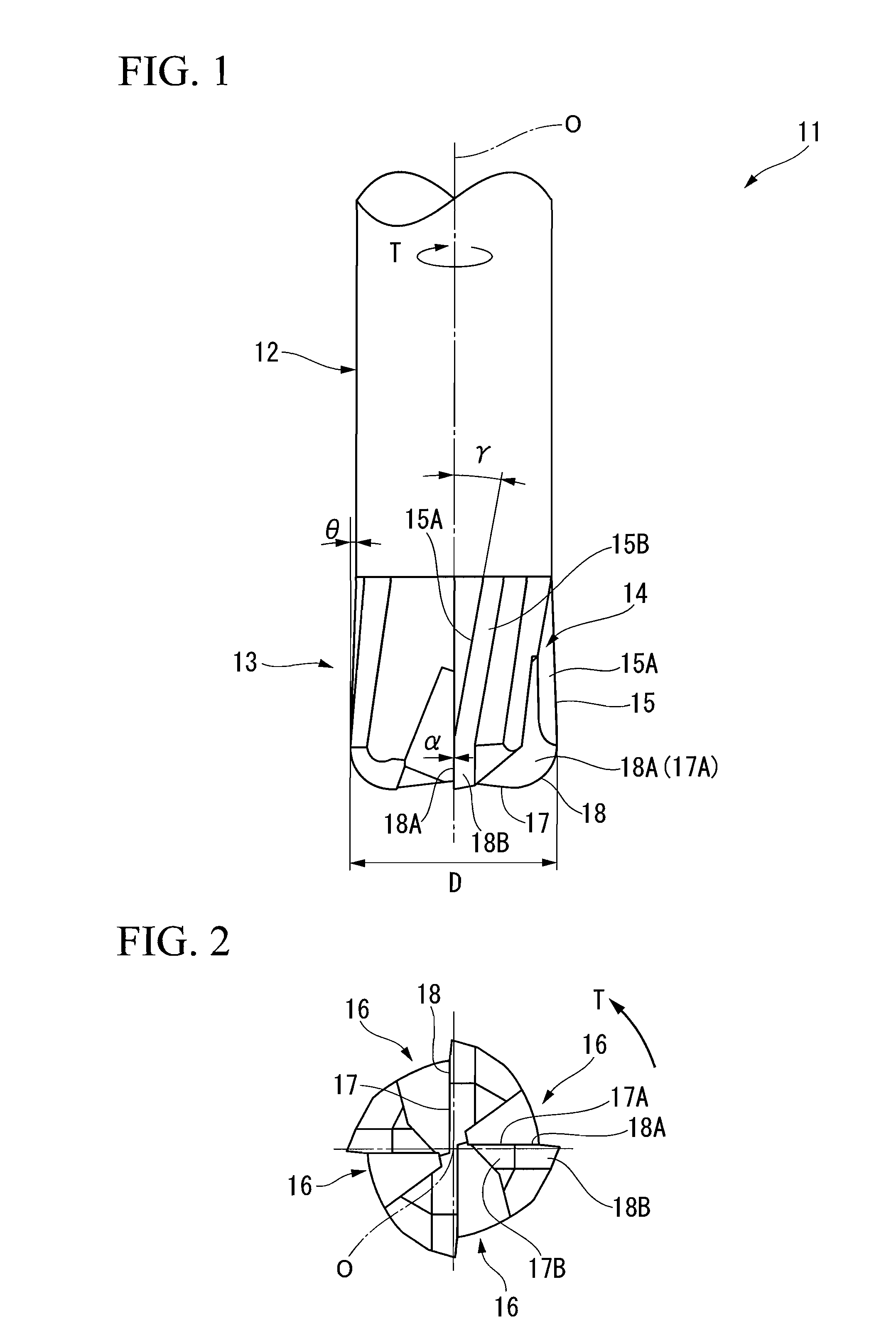
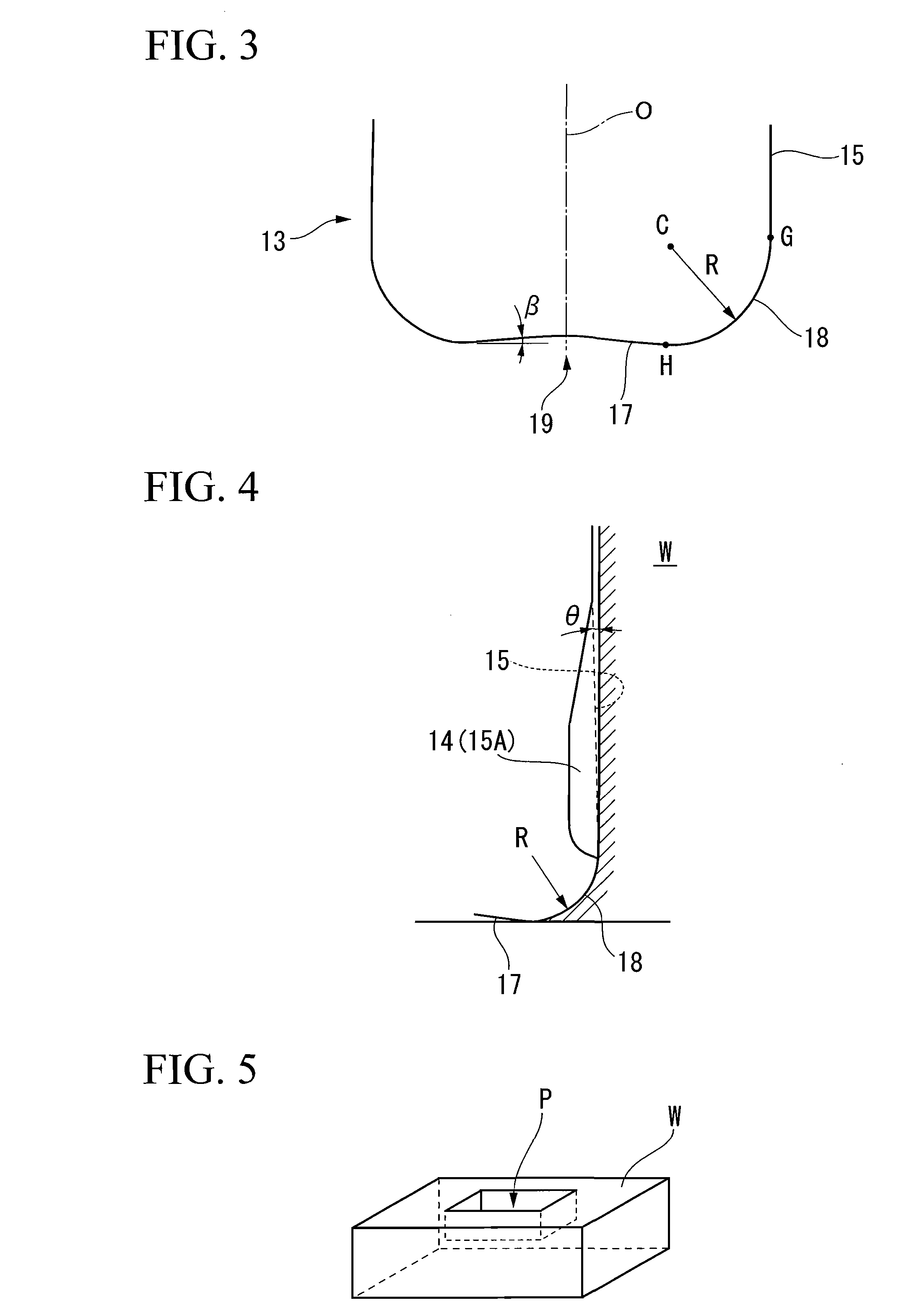
[0029]An embodiment of the radius end mill of the present invention will be explained with reference to attached figures. In each of FIG. 1 to FIG. 3, the embodiment of the radius end mill of the present invention is disclosed. In FIG. 4, angle parts and an outline part of a material to be cut is disclosed when the pocket is formed in the material using the radius end mill of this embodiment.

[0030]An end mill body 11 is made of solid material such as ultrahard alloy. As shown in FIG. 1, the end mill body 11 is formed like a cylindrical solid column center on an axis O. A part (upper part of the end mill 11 shown in FIG. 1) of the end mill body 11 located close to a terminal end thereof is provided with a shank portion 12 which is for attaching the end mill body 11 to an end of a main shaft of a machine tool. A part (on the lower part of the end mill 11 shown in FIG. 1) of the end mill body 11 located close to a distal end thereof is provided with cutting edge portion 13.

[0031]The cu...


PUM

PropertyMeasurementUnit
rake angleaaaaaaaaaa
angleaaaaaaaaaa
twist angleaaaaaaaaaa

Abstract

An end mill body rotatable around an axis; peripheral cutting edges formed at a periphery of the end mill body located close to a distal end thereof; bottom cutting edges formed at a distal end of the end mill body; and corner cutting edges formed between the peripheral cutting edge and the bottom cutting edge. The corner cutting edges are formed to curve inwardly in a radial direction of the end mill body as they approach the distal end of the end mill body from the terminal end thereof and curve toward the terminal end of the end mill body after reaching the distal end of the end mill body. The bottom cutting edges are formed to communicate with the corner cutting edges and are close to the terminal end of the end mill body as the bottom cutting edge approaches inwardly in the radial direction. A value of a rake angle α of the corner cutting edge with respect to the axis −10°≦α≧10°. A rake surface of the corner cutting edge and a rake surface of the bottom cutting edge each are formed like a plane, and the rake surface of the corner cutting edge is formed to be flush with the rake surface of the bottom cutting edge. When an external diameter of the end mill body is D, a value of a curvature radius R of the corner cutting edge is greater than or equal to 0.1×D and is less than or equal to 0.3×D.

Description

CROSS REFERENCE TO PRIOR APPLICATION[0001]This is a U.S. national phase application under 35 U.S.C. §371 of International Patent Application No. PCT / JP2006 / 314665 filed Jul. 25, 2006, which claims the benefit of Japanese Patent Application No. 2005-214210 filed Jul. 25, 2005, both of which are incorporated by reference herein. The International Application was published in Japanese on Feb. 1, 2007 as WO 2007 / 013447 A1 under PCT Article 21(2).TECHNICAL FIELD[0002]This invention relates to a radius end mill used to cut an object to form a mold or the like, and a cutting method using the radius end mill.BACKGROUND OF THE INVENTION[0003]Conventional radius end mill includes chip ejection grooves, peripheral cutting edges, bottom cutting edges and corner cutting edges. For example, each of the chip ejection grooves is formed at a peripheral portion of an end mill body located close to a distal end of the body so as to be twisted backward in the rotation direction of the end mill as the c...

Claims


Application Information

Patent Timeline
Patent Type & Authority Applications(United States)
IPC IPC(8): B23C5/10B23C5/14
CPCB23C5/10B23C2210/0407B23C2210/126Y10T407/23Y10T409/303752Y10T407/1966Y10T407/1948B23C2210/54B23C5/00
Inventor AOKI, TAIITSUABE, KAZUMASA
Owner MITSUBISHI MATERIALS CORP
Why Eureka
Try Eureka