

Inner flame burner for regeneration of diesel particulate filter
- Summary
- Abstract
- Description
- Claims
- Application Information
AI Technical Summary
Benefits of technology
Problems solved by technology
Method used
Image

Examples
first embodiment
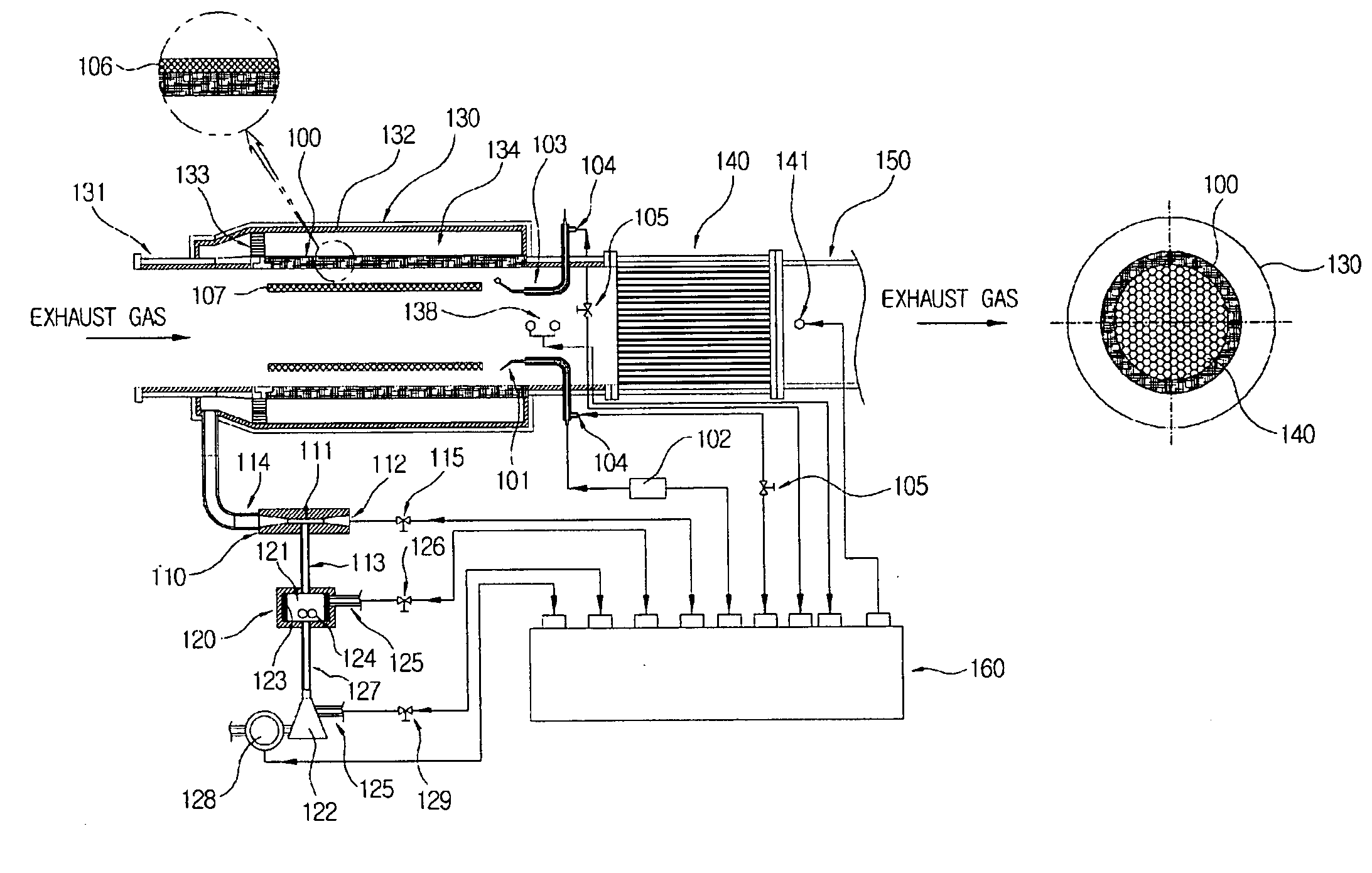
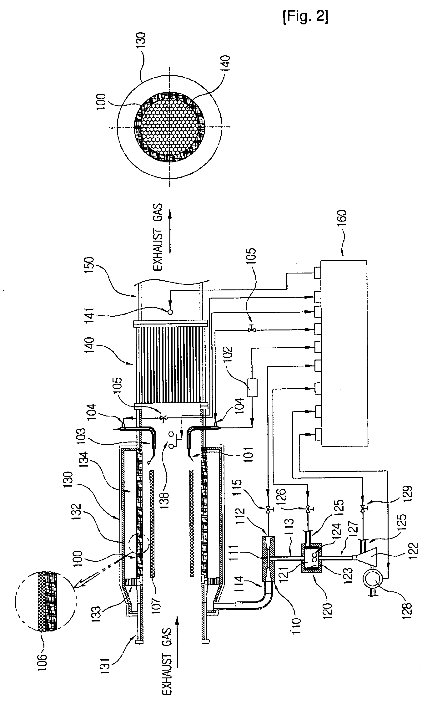
[0047]FIG. 2 is a diagram illustrating a diesel particulate filter having a burner for regenerating the diesel particulate filter according to the present invention.
[0048]Referring to FIG. 2, the burner for regenerating the diesel particulate filter according to the first embodiment includes one end connected to an exhaust gas channel through at least one of connecting pipes 131 and other end connected to a particulate filtering device such as a filter 140 for collecting soot particles. The burner according to the first embodiment includes an inner flame combustor 100 made of porous mat type metal fiber for burning gasified fuel, a carburetor 120 for gasifying fuel to supply the gasified fuel to the inner flame combustor 100, a mixed gas supplying unit 110 for mixing the gasified fuel from the carburetor 120 and an external air for burning and supplying the mixed gas to the inner flame combustor 100, a combustion chamber 130 where the inner flame combustor 100 is disposed and receiv...
second embodiment
[0074]That is, the injecting speeds become varied by the influence of the pressure distribution in the length direction of the mixed gas storing chamber because the distance between the inner flame combustor 100 and the side wall of the combustion chamber 130 is constant. In the burner the flow-rate uniform unit 135 disposed in the mixed gas storing chamber 134 for eliminating the influence of the pressure distribution in the length direction.
[0075]Hereinafter, a burner for regenerating a diesel particulate filter according to the third embodiment of the present invention will be described with reference to FIGS. 4 through 7. Since the burner according to the third embodiment has the similar structure compared to the burners according to the first and the second embodiments, the detailed descriptions of the identical elements will be omitted.
third embodiment
[0076]When the exhaust gas flows from the diesel engine into the combustion chamber, the burner swirls the exhaust gas in order to maximize the regeneration efficiency.
[0077]Since the flames formed on the inner flame combustor 100 are formed along edges of the combustion chamber 130, which is the outside of the exhaust gas flow, the flames are not influenced by the exhaust gas flow variation. The heat is transferred from the flames to the exhaust gas mainly through radiant heat-exchanging with a convention current. Herein, the heat transfer mechanism between the flames and the exhaust gas significantly influences the level of increasing an exhaust gas temperature and the time of increasing the exhaust gas temperature. If the flow of the exhaust gas is swirling, the heat transfer mechanism may have superior characteristics in the view of heat and material transfer. The centrifugal force made by swirling moves soot particles in the exhaust gas to the edges of the combustion chamber 1...
PUM
 Abstract
Description
Claims
Application Information