Structural oil baffle for engine covers

a technology of engine covers and structural rigidity, applied in the direction of crankcase compression engine lubrication, lubricant mounting/connection, separation process, etc., can solve the problems of increasing net oil consumption, contributing to the overall noise radiated by an internal combustion engine, and degrading engine emission quality, so as to reduce the vibration of the cover surface, increase the effect of structural rigidity and reduce the effect of surface vibration

Active Publication Date: 2010-06-17
FORD GLOBAL TECH LLC
View PDF11 Cites 16 Cited by
  • Summary
  • Abstract
  • Description
  • Claims
  • Application Information

AI Technical Summary

Benefits of technology

[0007]In this way various example valve covers in accordance with the present disclosure may have a high structural rigidity. In addition, various example valve covers in accordance with the present disclosure may include an attachment pattern connecting the cam cover to the oil baffle that may add to its effectiveness in reducing cover surface vibration and cover radiated noise.
[0008]In this way, the amount of noise and vibration that may be radiated by the v

Problems solved by technology

However, combustion of the oil may cause the net oil consumption to increase, as well as degrade engine emission quality.
However, one potential problem with cam covers and oil baffles is that they may be contributors to the overall noise radiated by an internal combustion engine during operation.
However, this increases the challenge of reducing engine noise because benchmarking and experience indicate that isolated cam covers made of composite mate

Method used


Image

  • Structural oil baffle for engine covers
  • Structural oil baffle for engine covers
  • Structural oil baffle for engine covers

Examples


Embodiment Construction

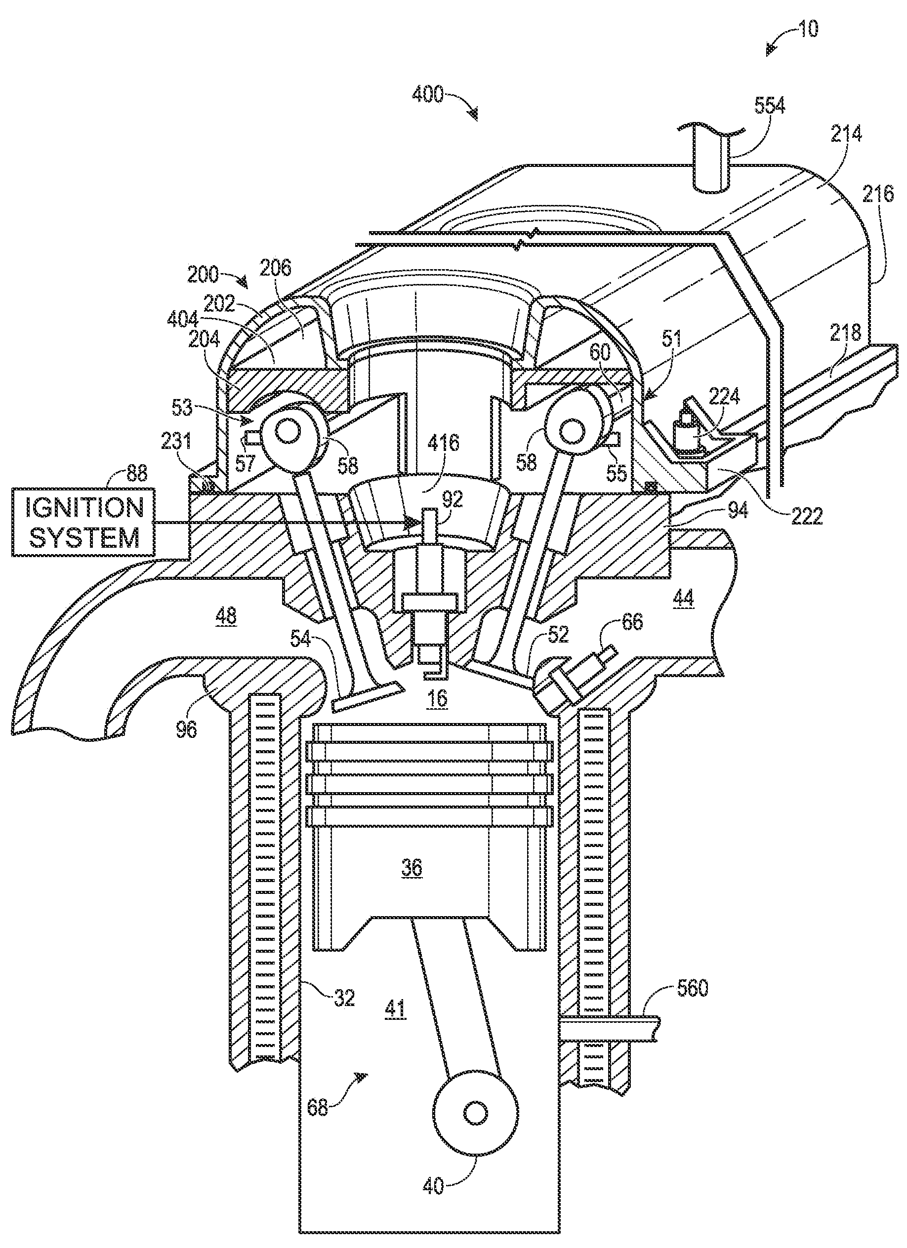
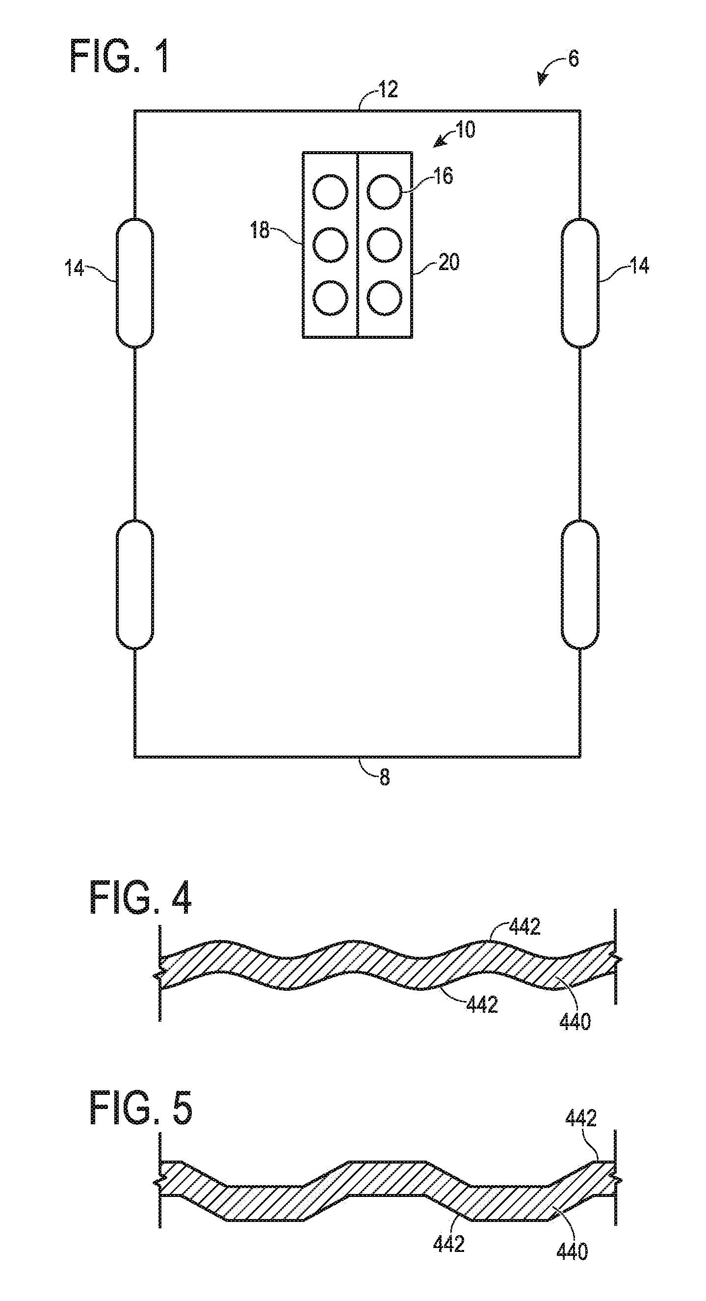
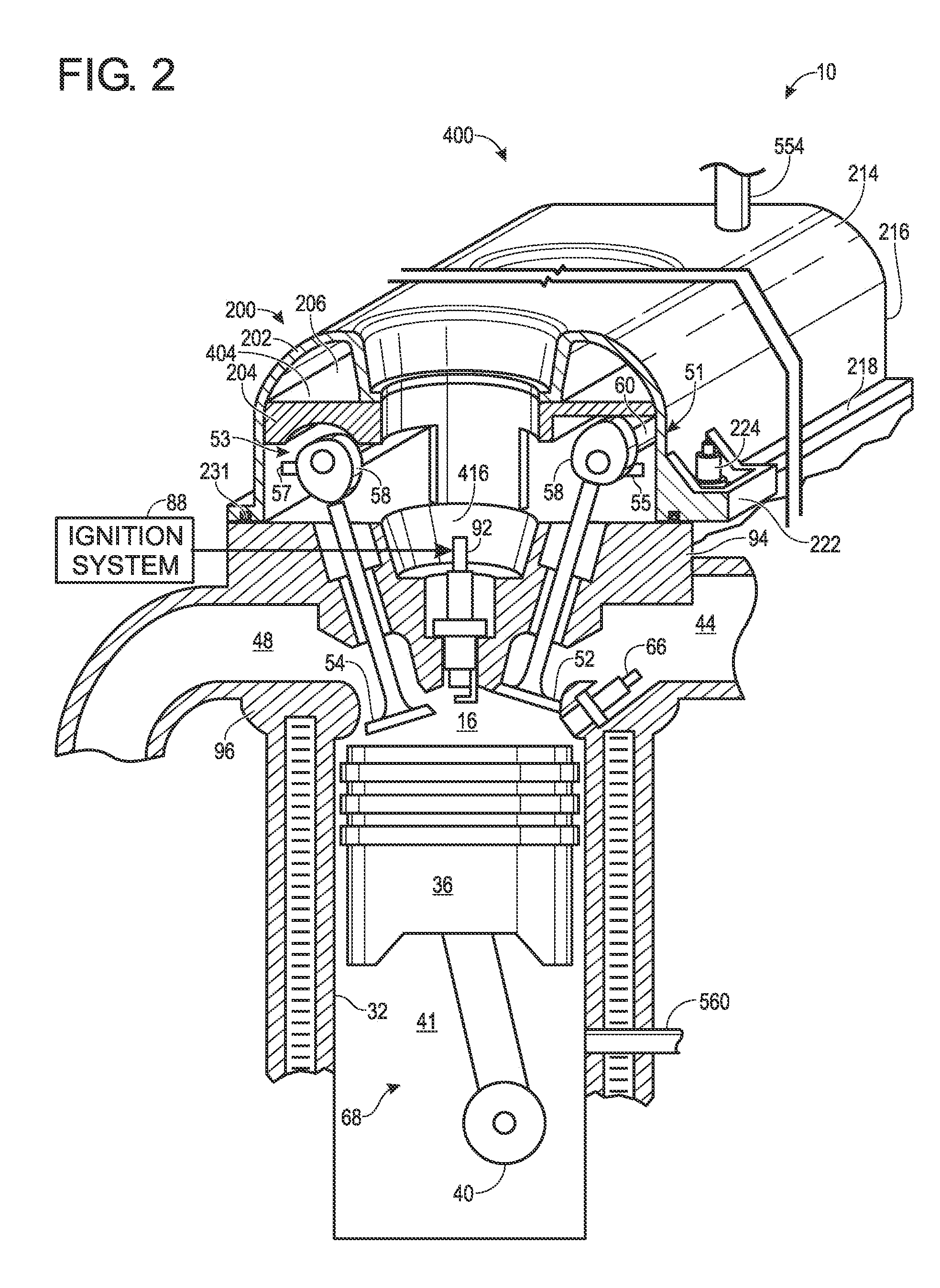
[0016]The following description relates to a system 6 for separating oil from blow-by gas in an engine 10 of a vehicle 8 as shown in FIG. 1. The system 6 may be mounted inside the engine 10, within a cam cover, and / or on top of a cylinder head. The system 6 of the present disclosure may include an oil baffle that may have sufficient rigidity and that may be coupled to the cam cover at locations and / or in a pattern that may make the system particularly effective in reducing the amount of vibration and noise from the engine.

[0017]The separated oil may be returned to the crankcase for lubricating a crankshaft, and / or sent to the camshaft assembly for lubricating the rotating cam lobes, camshaft and / or the valve assembly. Various parameters of the oil separator may be tuned to different engines based on the desired oil challenge, oil particle size, and an oil consumption target. Thus, an oil separator of the disclosed configuration may enable efficient oil separation and improved NVH is...


PUM

PropertyMeasurementUnit
Areaaaaaaaaaaa
Perimeteraaaaaaaaaa

Abstract

An oil baffle, a system, and a method are disclosed for separating a gaseous component from oil in a blow-by vapor for an internal combustion engine. An example system may include a cam cover configured to be mounted on a cylinder head. The system may also include an oil baffle that may have a generally planar body with a first face and a second face opposite the first face. The first face may be coupled to the cam cover and may define an oil separation chamber between the cam cover and the first face. The oil baffle may include one or more stiffening members coupled to and extending from and substantially normal to the second face.

Description

FIELD[0001]The present application relates to an oil baffle provided in an internal combustion engine to separate oil from blow-by gases having improved vibration isolation, and noise abatement characteristics.BACKGROUND AND SUMMARY[0002]When an air-fuel mixture is combusted in an engine combustion chamber, a small portion of the combusted gas may enter the engine crankcase through the piston rings. This gas is referred to as blow-by gas. To prevent this untreated gas from being directly vented into the atmosphere, a crankcase ventilation system is provided between the higher pressure crankcase and the lower pressure intake manifold to allow the blow-by gas to flow from the crankcase into the intake manifold and be mixed with fresh air. From here, the gas may be re-inducted into the combustion chamber for re-combustion.[0003]Engine lubrication oil used to lubricate moving parts of the engine is present in the crankcase during normal engine operation. The high pressure in the crankca...

Claims


Application Information

Patent Timeline
IPC IPC(8): F01M13/04F01M3/00F01M3/02
CPCF01M13/0416F02B77/00F02F7/006F01M2013/0461
Inventor FESTAG, GEORGCIERPIAL, PHILIP DAMIANBAGHDADI, ABDELHAKIM
Owner FORD GLOBAL TECH LLC
Why Eureka
Try Eureka