Glow plug with pressure sensing canister

a technology of pressure sensing canister and glow plug, which is applied in the direction of combustion process, lighting and heating apparatus, combustion ignition, etc., can solve the problem of direct change of pressure sensor force, and achieve the effect of short length, high cross-sectional area, and relatively low initial preload for

Inactive Publication Date:
View PDF6 Cites 27 Cited by
  • Summary
  • Abstract
  • Description
  • Claims
  • Application Information

AI Technical Summary

Benefits of technology

[0013]The subject invention, addresses the prior art shortcomings in that it does not depend on the electrode to transmit forces to or from the pressure sensor. Rather, the electrode passes through the pressure sensor generally untouched. This is distinguished from prior art systems like that depicted in FIG. 2. According to this invention, the pressure sensor is effectively placed directly onto the base end of the heater probe and pressed against it using a canister which surrounds the pressure sensor to form a containment capsule. The canister is rigidly connected to the shell preferably very near to its seat. Because the heater probe moves in response to pressure fluctuations but the shell does not, movement of the heater probe leads directly to changing forces on the pressure sensor. As force increases with applied gas pressure, the initial preload force can be relatively low. The force carrying elements can thus have a short length and high cross-sectional area, giving high stiffness and hence a high degree of sensor sensitivity. The canister can be designed with a short length and, owning to its enclosed nature, gives additional benefits of good thermal performance due to reduced differences in thermal expansion, which further contributes to a low starting preload. Electrical connections can be brought out as an easily accessible, coaxial configuration if desired. Manufacturing is aided by the alignment inherent in the assembly being inside the canister. The connection of the canister to the shell of the glow plug is arranged, preferably, to be very close to the end of the shell, i.e., near the seat, thereby minimizing signal distortion due to changing forces in the external shell of the glow plug.

Problems solved by technology

Because the heater probe moves in response to pressure fluctuations but the shell does not, movement of the heater probe leads directly to changing forces on the pressure sensor.

Method used


Image

  • Glow plug with pressure sensing canister
  • Glow plug with pressure sensing canister
  • Glow plug with pressure sensing canister

Examples


Embodiment Construction

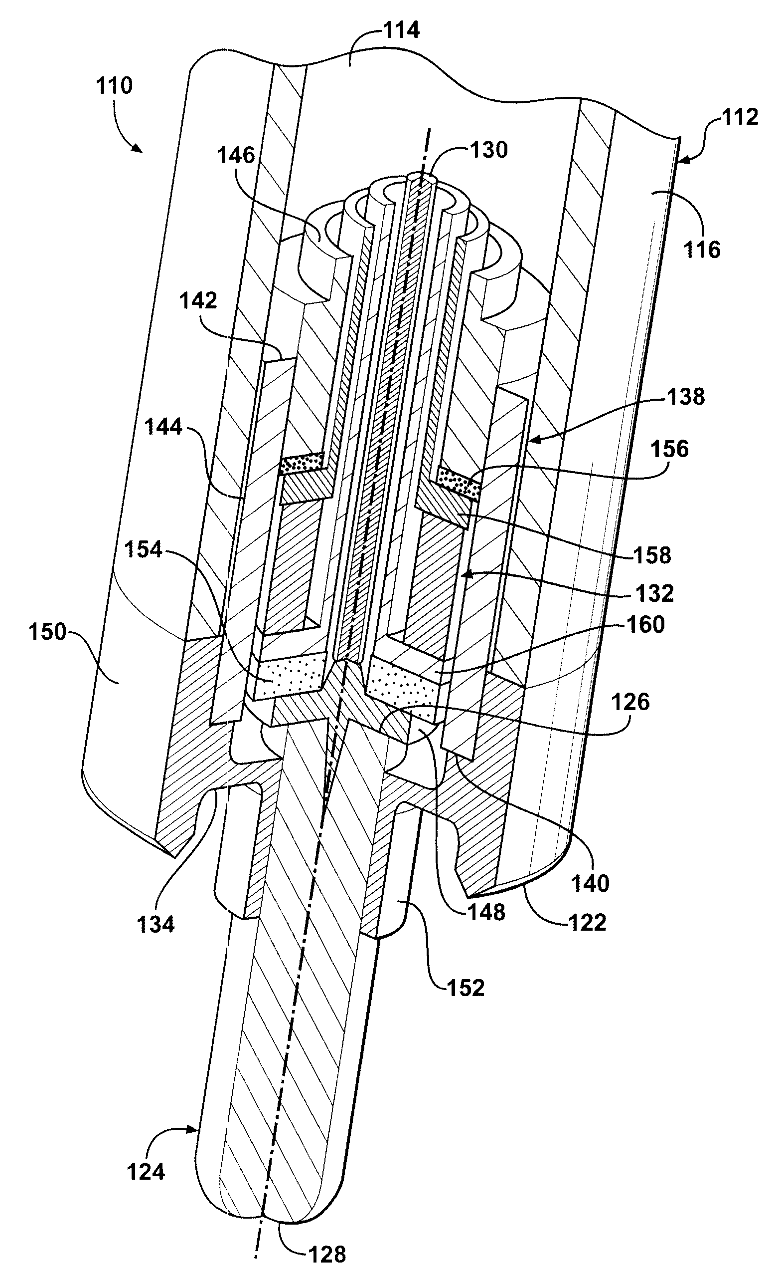
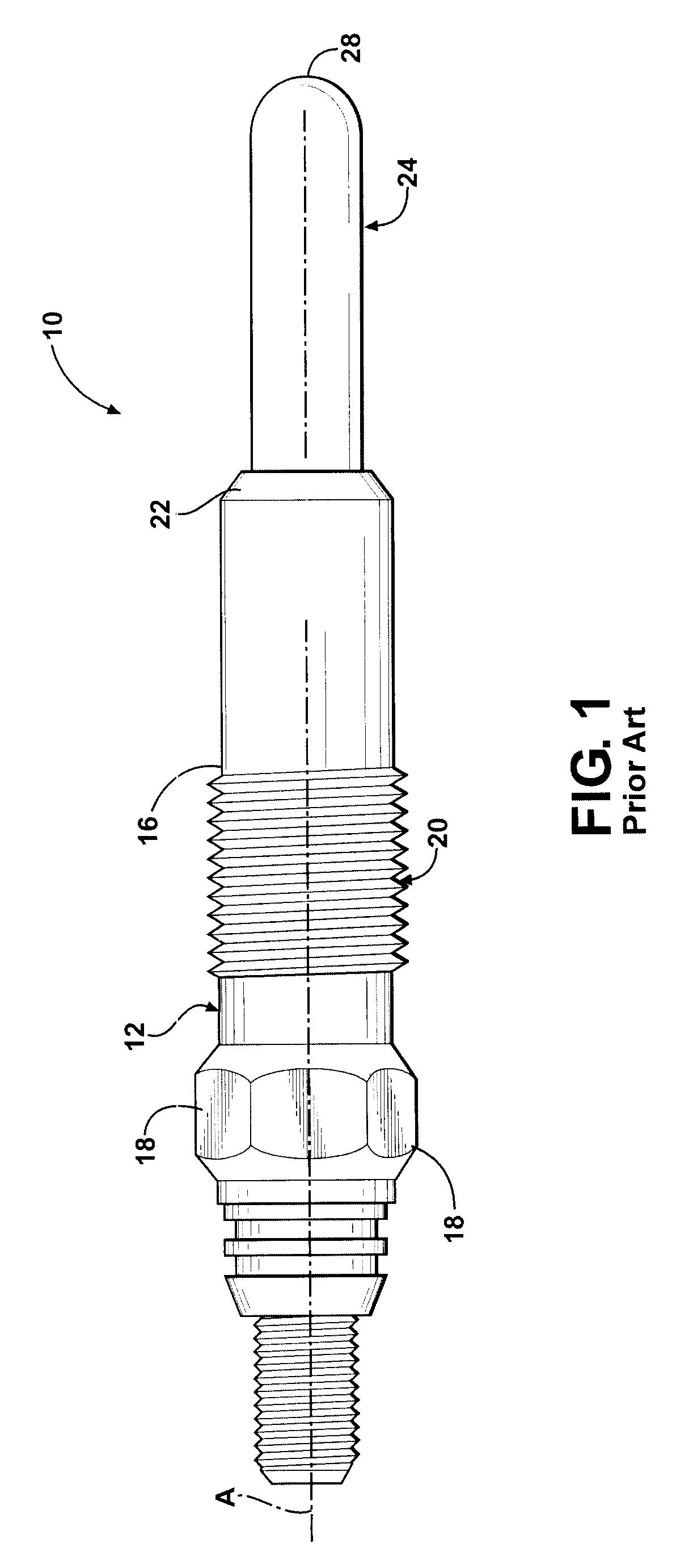
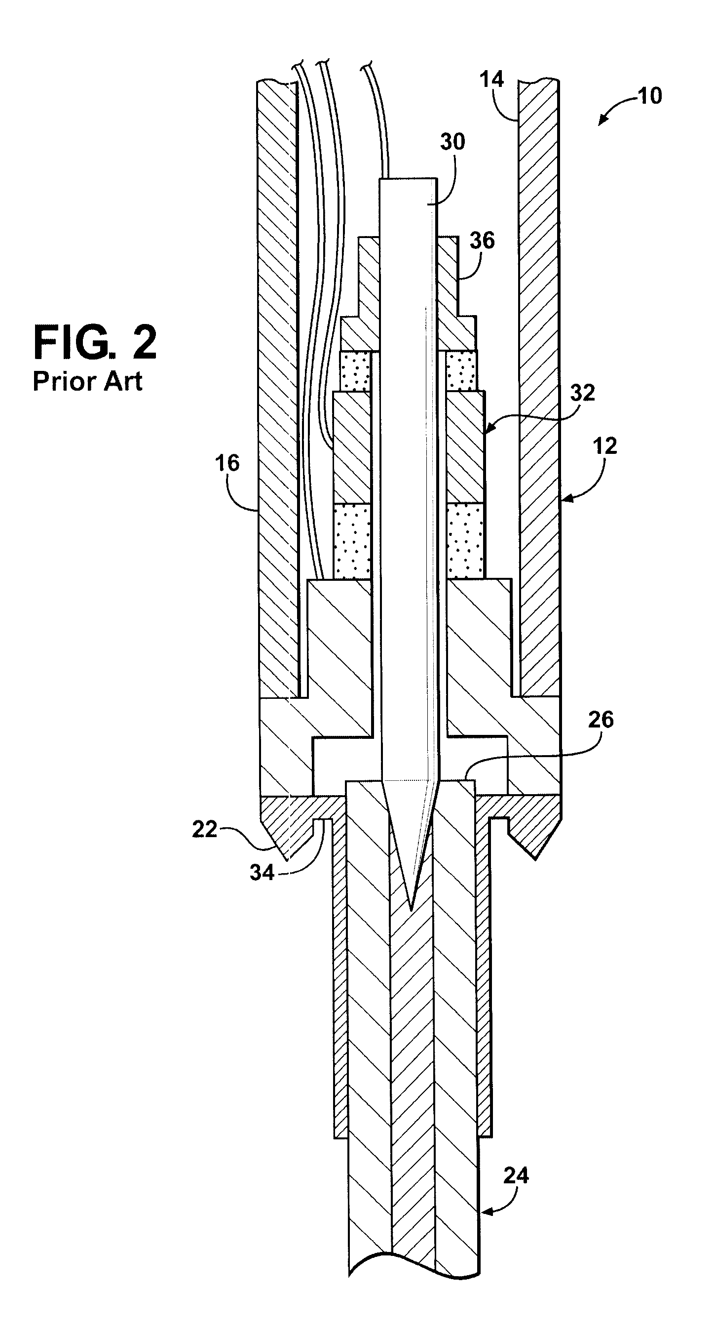
[0024]Referring to the Figures, wherein like numerals indicate like or corresponding parts throughout the several views, a glow plug according to the prior art is generally shown at 10 in FIGS. 1 and 2. The glow plug 10 includes an annular metal shell 12 having a bore 14 which extends along an imaginary longitudinal axis A. The shell 12 may be formed from any suitable metal, such as various grades of steel. The shell 12 may also incorporate a plating or coating layer, such as a nickel or nickel alloy coating over some or all of its surfaces including the exterior surface 16 and within the bore 14 so as to improve its resistance to high temperature oxidation and corrosion. The shell 12 includes external wrenching flats 18 or other suitably configured tool-receiving portion to advance screw threads 20 into an appropriately tapped hole in an engine cylinder head, pre-ignition chamber, intake manifold or the like. A tapered seat 22 bears against a complimentary-shaped pocket in the mati...


PUM

PropertyMeasurementUnit
pressureaaaaaaaaaa
compressive preload forceaaaaaaaaaa
pressure-aaaaaaaaaa

Abstract

A glow plug assembly includes an integrated, internal pressure sensor. In order to reduce loading on the center electrode, improve sensor responsiveness, and provide better thermal performance, the pressure sensor assembly is housed in a canister which forms a containment capsule and rigidly connects inside the glow plug shell near its seat area. The pressure sensor makes direct contact with the base end of the heater probe so that movements of the heater probe caused by fluctuations in gas pressure lead directly to changing force on the sensor stack.

Description

CROSS REFERENCE TO RELATED APPLICATIONS[0001]None.BACKGROUND OF THE INVENTION[0002]1. Field of the Invention[0003]This invention relates to a glow plug, and more particularly toward a glow plug having an integrated pressure sensing device for use in an internal combustion engine.[0004]2. Related Art[0005]Glow plugs are typically used in applications where a source of intense heat is required to either directly initiate or to aid in the initiation of combustion. As such, glow plugs are used in space heaters, industrial furnaces and diesel engines to name a few.[0006]In the field of compression ignition engines, there are trends toward ever greater output and efficiency, as well as toward the use of flexible fuels, which together have increased the demand for and usage of various types of combustion sensors necessary to enable enhanced control of the engine and combustion processes. Combustion sensors, particularly combustion pressure sensors, have in the past been discrete sensors th...

Claims


Application Information

Patent Timeline
Patent Type & Authority Applications(United States)
IPC IPC(8): F23Q7/22H05B3/00G01M15/00
CPCF02P19/028F23Q7/001Y10T29/49083G01L23/10F23Q2007/002F02P19/00F23Q7/22F02P19/02
Inventor BURROWS, JOHN A.GORETTI, SANDRO
Why Eureka
Try Eureka